3 If the ground potential between the drive and the PLC is
dierent, electric noise can occur that disturbs the entire
system. Fit an equalizing cable next to the control cable.
Minimum cable cross-section: 16 mm
2
(6 AWG).
4 If long control cables are used, 50/60 Hz ground loops are
possible. Connect 1 end of the shield to ground via a 100
nF capacitor (keeping leads short).
5 When using cables for serial communication, eliminate
low-frequency noise currents between 2 drives by
connecting 1 end of the shield to terminal 61. This
terminal is connected to ground via an internal RC link.
Use twisted-pair cables for reducing the dierential mode
interference between the conductors.
Illustration 7.5 Grounding Examples
7.4.1 Control Cable Routing
Tie down and route all control wires. Remember to
connect the shields in a proper way to ensure optimum
electrical immunity.
•
Isolate control wiring from high-power cables.
•
When the drive is connected to a thermistor,
ensure that the thermistor control wiring is
shielded and reinforced/double insulated. A
24 V DC supply voltage is recommended.
Fieldbus connection
Connections are made to the relevant options on the
control card. See the relevant eldbus instruction. The
cable must be tied down and routed along with other
control wires inside the unit.
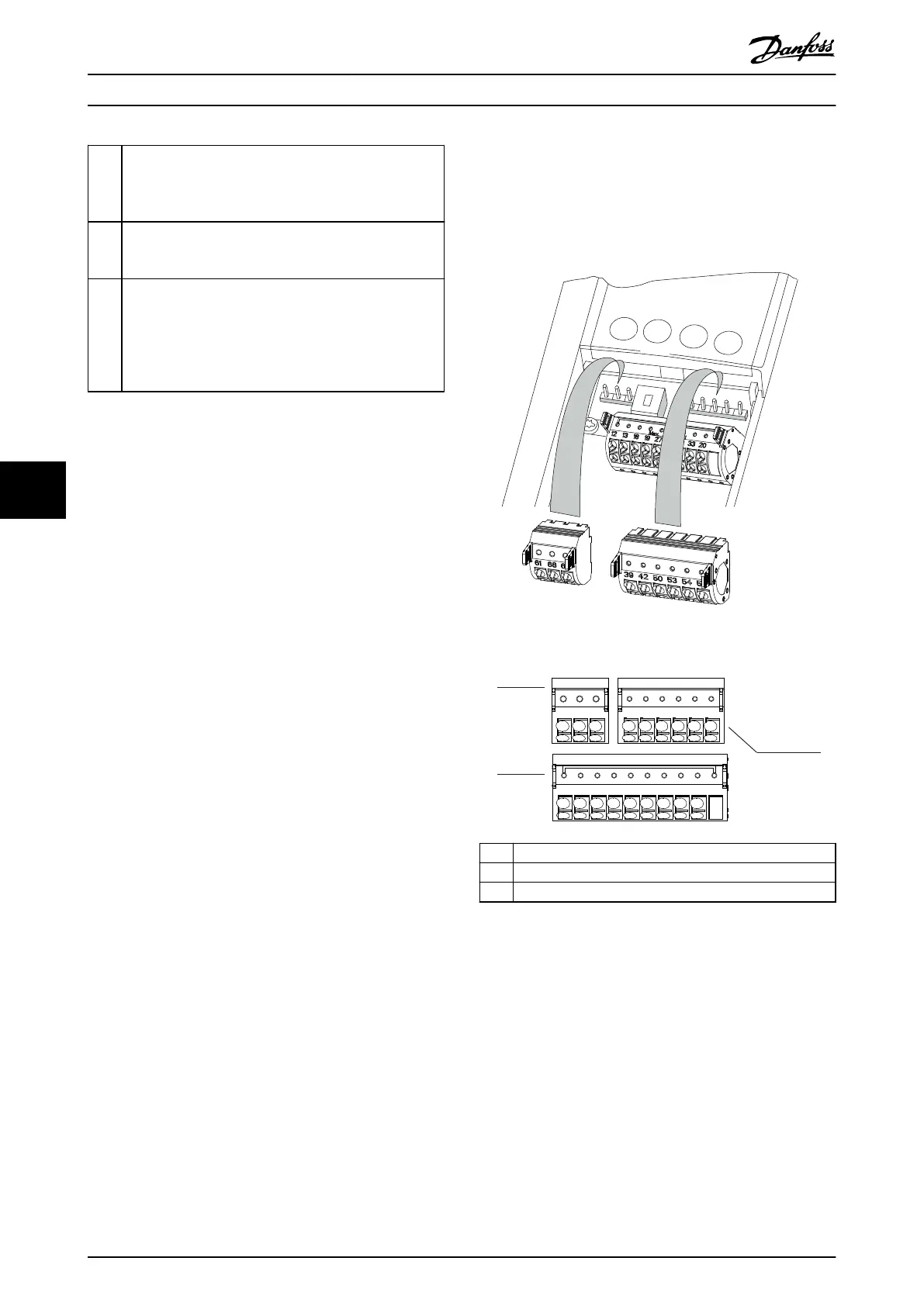
7.4.2 Control Terminals
Illustration 7.6 shows the removable drive connectors.
Terminal functions and default settings are summarized in
Table 7.2 – Table 7.4.
Illustration 7.6 Control Terminal Locations
12 13 18 19 27 29 32 33 20
39696861 42 50 53 54 55
e30bg502.11
1
2
3
1 Serial communication terminals
2 Digital input/output terminals
3 Analog input/output terminals
Illustration 7.7 Terminal Numbers Located on the Connectors
Electrical Installation Con... VLT® AutomationDrive FC 361
42 Danfoss A/S © 03/2019 All rights reserved. MG06K102
77
 Loading...


