Callout Key Function
C1 Back Reverts to the previous step or list in the
menu structure.
C2 Cancel Cancels the last change or command as
long as the display mode has not changed.
C3 Info Shows a denition of the function being
shown.
C4 OK Accesses parameter groups or enables an
option.
C5
▲
▼
◄►
Moves between items in the menu.
Table 4.3 Legend to Illustration 4.1, LCP Navigation Keys
D. Indicator lights
Indicator lights are used to identify the drive system status
and to provide a visual notication of warning or fault
conditions.
Callout Indicator Indicator
light
Function
D1 On Green Activates when the drive system
receives power from the mains
voltage or a 24 V external
supply.
D2 Warn. Yellow Activates when warning
conditions are active. Text
appears in the display area
identifying the problem.
D3 Alarm Red Activates during a fault
condition. Text appears in the
display area identifying the
problem.
Table 4.4 Legend to Illustration 4.1, LCP Indicator Lights
E. Operation keys and reset
The operation keys are found toward the bottom of the
local control panel.
Callout Key Function
E1 Hand On Starts the drive system in local control.
An external stop signal by control input
or serial communication overrides the
local hand on.
E2 O Stops the motor but does not remove
power to the drive system.
E3 Auto On Puts the system in remote operational
mode so it can respond to an external
start command by control terminals or
serial communication.
E4 Reset Resets the drive system manually after a
fault has been cleared.
Table 4.5 Legend to Illustration 4.1, LCP Operation Keys, and
Reset
4.3.3 Menus
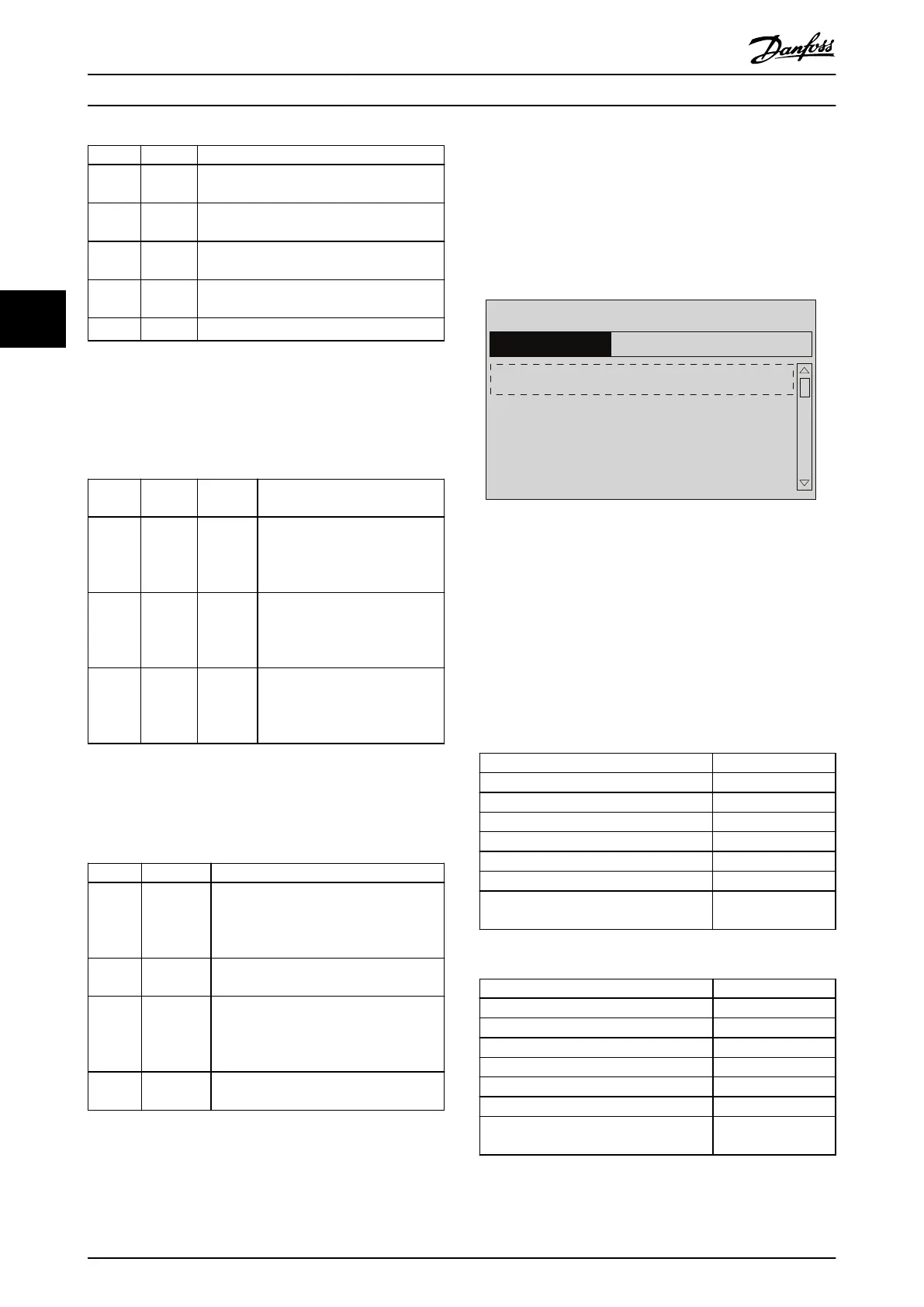
4.3.3.1 Quick Menu Mode
The LCP provides access to all parameters listed under the
Quick Menus. To show the list of options in the Quick
Menu, press [Quick Menu].
130BE057.10
01 My Personal Menu
02 Quick Setup
05 Changes Made
06 Loggings
0.0% 0.00
Quick Menus
1(1)
Illustration 4.2 Quick Menu View
4.3.3.2 Q1 My Personal Menu
The Personal Menu is used to dene the LCP readout
display (see chapter 4.3.2 Layout) and store pre-selected
parameters. Use up to 20 pre-programmed parameters to
store important setup values, thus simplifying on-site
commissioning and ne-tuning for large-scale applications.
These parameters are selected in parameter 0-25 My
Personal Menu.
Parameter Default setting
Parameter 0-01 Language English
Parameter 0-20 Display Line 1.1 Small Reference %
Parameter 0-21 Display Line 1.2 Small Motor Current
Parameter 0-22 Display Line 1.3 Small Power [kW]
Parameter 0-23 Display Line 2 Large Frequency
Parameter 0-24 Display Line 3 Large kWh Counter
Parameter 15-51 Frequency Converter Serial
Number
–
Table 4.6 Q1 My Personal Menu Settings, FC 102
Parameter Default setting
Parameter 0-01 Language English
Parameter 0-20 Display Line 1.1 Small Reference [Unit]
Parameter 0-21 Display Line 1.2 Small Analog Input 53
Parameter 0-22 Display Line 1.3 Small Motor Current
Parameter 0-23 Display Line 2 Large Frequency
Parameter 0-24 Display Line 3 Large Feedback [Unit]
Parameter 15-51 Frequency Converter Serial
Number
–
Table 4.7 Q1 My Personal Menu Settings, FC 202
Commissioning
VLT
®
Parallel Drive Modules
16 Danfoss A/S © 08/2017 All rights reserved. MG37L202
44
 Loading...


