4.4.2 Q3 Function Set-ups
The Function Set-up provides quick and easy access to all
parameters required for most applications. Among other
features, it also includes parameters for selecting which
variables to display on the LCP, digital preset speeds,
scaling of analog references, closed loop single-zone and
multi-zone applications, and functions specically related
to the applications. For more on Function Set-up, including
programming examples, refer to the operating instructions
and programming guides applicable to the VLT
®
HVAC
Drive FC 102, VLT
®
AQUA Drive FC 202, or VLT
®
AutomationDrive FC 301/FC 302 series of VLT
®
Parallel
Drive Modules used in the drive system.
4.4.3 Control Terminal Programming
The control terminals can be programmed using the LCP.
•
Each terminal has specied functions it can
perform.
•
Parameters associated with the terminal enable
the function.
•
For proper drive system functioning, the control
terminals must be:
- Wired properly.
- Programmed for the intended function.
- Receiving a signal.
See Table 8.2 for control terminal parameter number and
default setting. (Default setting can change based on the
selection in parameter 0-03 Regional Settings).
The following example shows how terminal 18 is accessed
to see the default setting:
1. Press [Main Menu] twice, scroll to parameter
group 5-** Digital In/Out Parameter Data Set and
then press [OK].
130BT768.10
2-** Brakes
3-** Reference / Ramps
4-** Limits / Warnings
5-** Digital In/Out
14.6% 0.00A 1(1)
Main Menu
Illustration 4.4 Main Menu Display Example
2. Scroll to parameter group 5-1* Digital Inputs and
then press [OK].
130BT769.10
5-0* Digital I/O mode
5-1* Digital Inputs
5-4* Relays
5-5* Pulse Input
14.7% 0.00A 1(1)
Digital In/Out
5-**
Illustration 4.5 Parameter Group Display Example
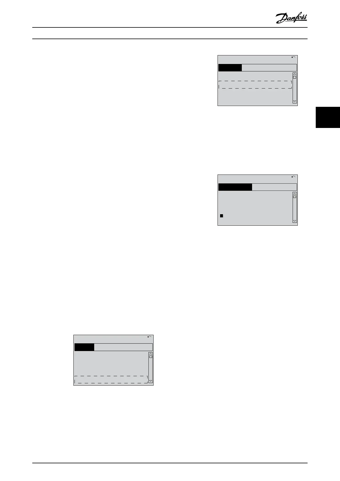
3. Scroll to parameter 5-10 Terminal 18 Digital Input.
Press [OK] to access function options. The default
setting Start is displayed. If this terminal must be
reprogrammed, the LCP can be used to access
the options available for this parameter and then
select a
dierent value.
5-1*
130BT770.10
5-10 Terminal 18 Digital
Input
[
8
]] Start
14.7% 0.00A 1(1)
Digital Inputs
Illustration 4.6 Function Choice Display Example
4.4.4 Conguring Automatic Energy
Optimization
Automatic energy optimization (AEO) is a procedure that
minimizes voltage to the motor, reducing energy
consumption, heat, and noise.
1. Press [Main Menu].
2. Select 1-** Load and Motor and press [OK].
3. Select 1-0* General Settings and press [OK].
4. Select parameter 1-03 Torque Characteristics and
press [OK].
5. Select either [2] Auto Energy Optim CT or [3] Auto
Energy Optim VT and press [OK].
4.4.5 Conguring Automatic Motor
Adaptation
Automatic motor adaptation (AMA) is a procedure that
optimizes compatibility between the drive system and the
motor.
During this procedure, the drive system builds a
mathematical model of the motor for regulating output
motor current. The procedure also tests the input phase
Commissioning User Guide
MG37L202 Danfoss A/S © 08/2017 All rights reserved. 19
4 4
 Loading...


