7.3.16 SCRs
1
2
3
4
5
6
7
8
9
10
12
13
14
15
11
130BX463.10
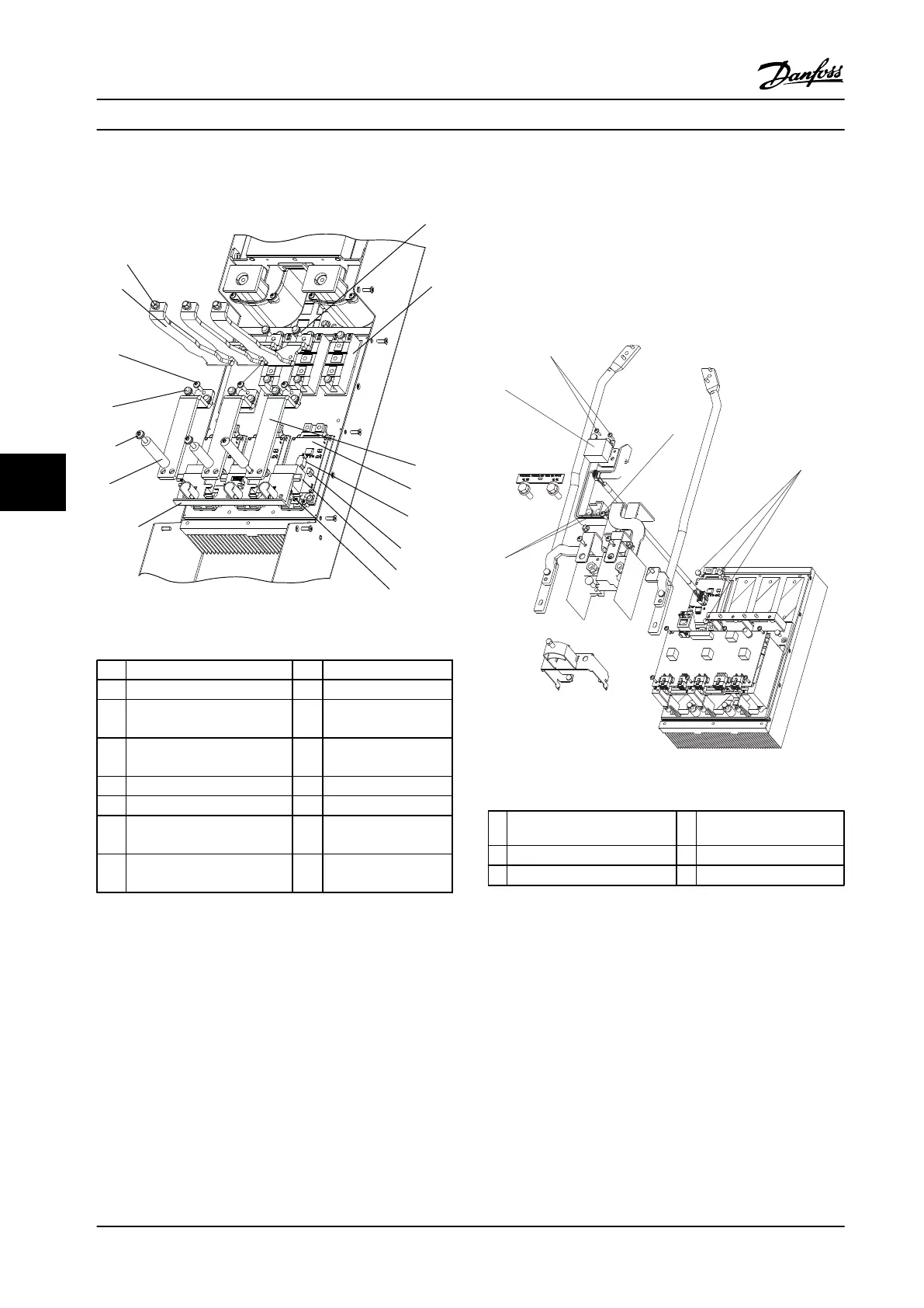
Figure 7.7 SCRs and IGBTs
1 SCR input bus bar 9 Snubber capacitor
2 0.4 in [10 mm] nut 10 T30 Screw
3 T30 screw 11 Round bus bar
support bracket
4 SCR 12 Current sensor
cylinder bus bar
5 IGBT output bus bar 13 T30 screw
6 IGBT module (1 of 3) 14 T30 screw
7 IGBT gate signal connector 15 T25 thread-forming
screw
8 IGBT thermal sensor
connector
Table 7.7 Legend to Figure 7.7
1. Remove the SCR input bus bars in accordance
with chapter 7.3.15 SCR Input Bus Bars.
2. Remove the (+) DC bus bar SCR to DC coil by first
removing one screw (T30) that attaches the bus
bar to the DC inductor.
3. Remove one screw (T30) from each SCR module.
For reassembly, use the replacement SCR instructions.
4. Remove the Mylar insulator and retain it for
reassembly.
5. Remove the (-) DC bus bar SCR to DC coil
following the same procedure as with the (+) DC.
6. Disconnect the gate leads, one from each SCR
module.
7. Remove one screw (T30) from either side of each
SCR module.
For reassembly, use the replacement SCR instructions.
7.3.17 Brake IGBT Module
Figure 7.8 Brake IGBT module
1
T20 thread-forming screws 4 T30 screws
2 T25 thread-forming screw 5 Snubber capacitor
3 T25 screws
Table 7.8 Legend to Figure 7.8
1. Remove the IGBT gate drive board in accordance
with chapter 7.3.14 IGBT Gate Drive Card.
2. Remove the line power terminal and motor
terminal in accordance with chapter 7.3.6 Line
Power Input Terminal Block and chapter 7.3.7 Motor
Terminal Block.
3. Remove the two brake to DC link bus bars in
accordance with chapter 7.3.12 DC Bus Rails.
4. Remove two thread-forming screws (T20) from
the top of the brake IGBT module.
5. Remove the brake snubber capacitor by removing
two screws (T30), one from each bus bar.
Disassembly and Assembly In...
Service Manual
98 Danfoss A/S © Rev. 2014-02-10 All rights reserved. MG94A222
77
 Loading...


