7.4.16 SCR Input Bus Bars
1
2
3
4
5
6
7
8
9
10
11
12
130BX455.10
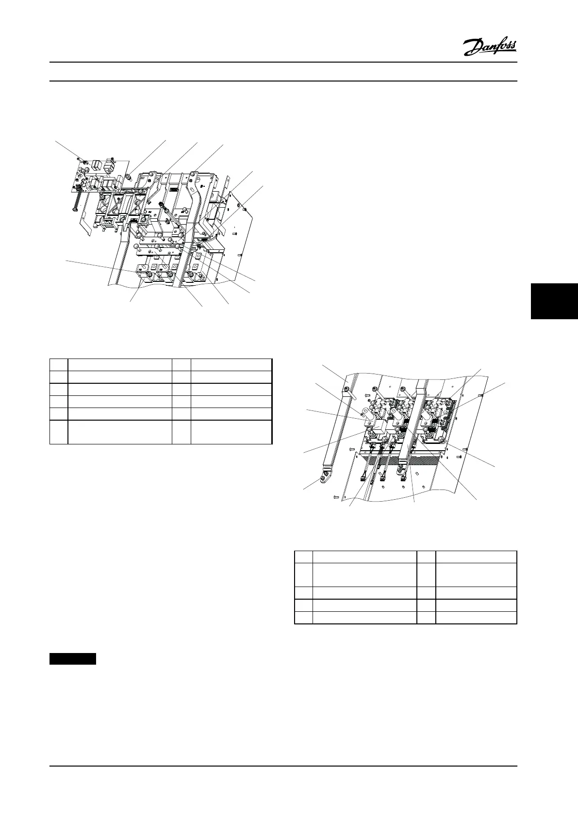
Figure 7.18 SCRs and SCR Input Bus Bars
1 Inrush card 7 T30 screw
2 0.6 in [16 mm] standoff 8 T50 screw
3 Inrush support bracket 9 SCR
4 T40 screw 10 (+) DC bus bar
5 (-) DC bus bar 11 SCR input bus bar
6 Gate lead 12 0.7 in [19 mm]
standoff
Table 7.18 Legend to Figure 7.18
1. Remove the inrush card in accordance with
chapter 7.4.15 Inrush Card.
2. Remove two screws (T20) from the middle of the
inrush card mounting bracket.
3. Remove two standoffs (0.6 in [16 mm]) from the
inrush card mounting bracket.
4. Remove three standoffs (0.7 in [19 mm])
connecting the bus bars to the SCR modules, one
for each SCR input bus bar.
5. Remove the bus bars.
Reinstall in reverse order of this procedure and tighten
hardware according to chapter 1.7 General Torque
Tightening Values.
NOTICE!
Note for reassembly: Fasten all components hand-tight
and then place the inrush support to align all before
tightening the fasteners.
7.4.17 SCRs
1. Remove the SCR input bus bars in accordance
with chapter 7.4.16 SCR Input Bus Bars.
2. Remove the (+) DC bus bar by removing the
three screws (T50), one from each SCR module.
3. Remove the (-) DC bus bar by removing the one
screw (T30) and three screws (T50), one from
each SCR modle.
4. Disconnect the gate leads, one from each SCR
module.
5. Remove one screw (T30) from each of the four
corners of each SCR module.
For reassembly, follow the replacement SCR instructions.
7.4.18
DC Bus Rails
7.4.18.1 Without Optional Brake
Figure 7.19 DC bus rails without brake option
1 (+) DC bus rail 6 (-) DC bus rail
2 IGBT module 7 T40 IGBT terminal
screw
3 IGBT output bus bar 8 0.4 in [10 mm] nut
4 T25 IGBT mounting screw 9 Snubber capacitor
5 T40 IGBT terminal screw 10 T20 screw
Table 7.19 Legend to Figure 7.19
Disassembly and Assembly In...
Service Manual
MG94A222 Danfoss A/S © Rev. 2014-02-10 All rights reserved. 109
7 7
 Loading...


