6.4.10 IGBT Switching Test
CAUTION
Before proceeding, remove input AC voltage and wait 20
minutes for the DC bus capacitors to discharge fully.
Provide power using the split bus power supply to
determine whether the IGBTs are switching correctly.
1. Connect the split bus power supply. See
chapter 8.1.1 Split Bus Power Supply.
2. Switch on the 650 V DC and 24 V DC power
supplies.
3. Apply a run command and speed command of
approximately 40 Hz.
4. Measure the phase to phase output waveform on
all three output phases of the adjustable
frequency drive using an oscilloscope (preferred)
or a voltmeter.
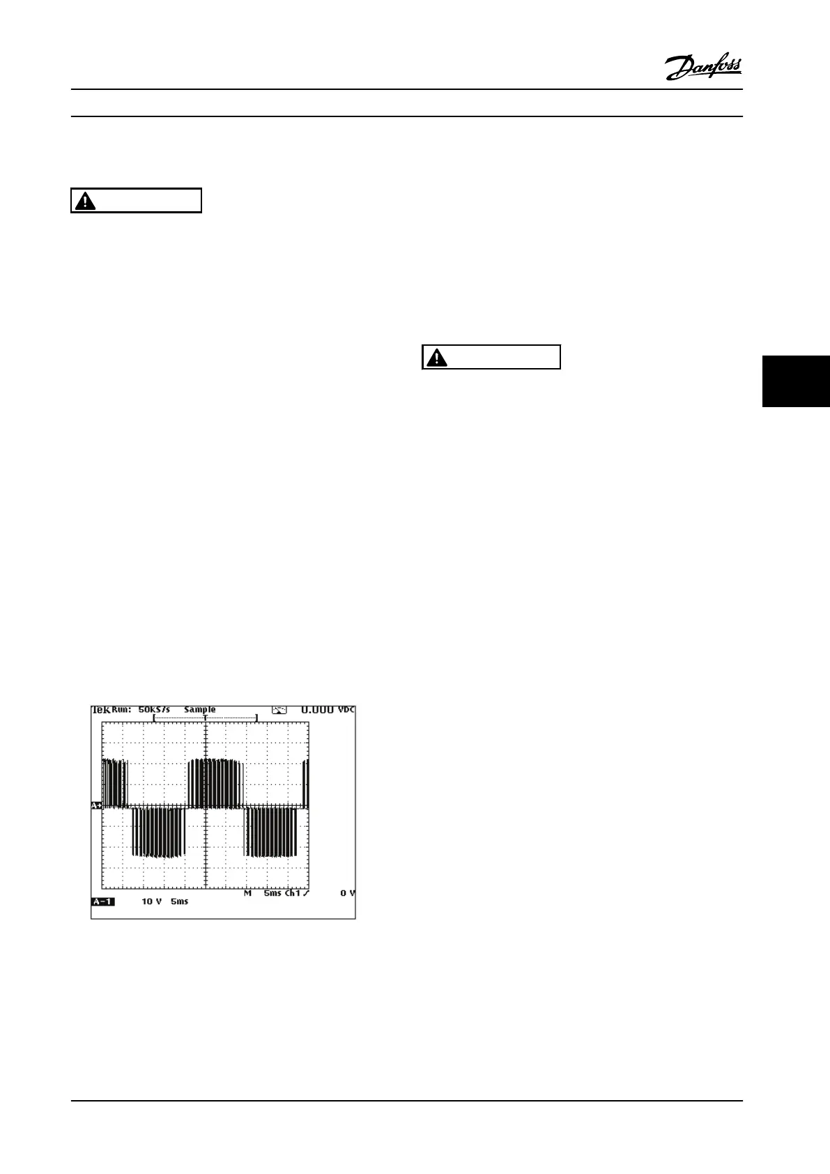
a. When measuring with an oscilloscope, the
waveform appears the same as in normal
operation, except that the amplitude is 24 V
peak. Figure 6.8
b. When measuring with a voltmeter set to read AC
voltage, the meter reads approximately 17 V AC
on all three phases. Differences in drive settings
could cause a slight variation in this reading but
it is important that the readings are equal on all
three phases.
Figure 6.8 Output Wave Form
An incorrect reading indicates either a defective IGBT or
gate drive signal. Perform the gate drive signal test (see
chapter 6.4.11 IGBT Gate Drive Signals Test) to determine if
the gate drive signal is correct.
6.4.11
IGBT Gate Drive Signals Test
This procedure tests the gate drive signals at the output of
the gate drive card just before they are delivered to the
IGBTs.
A simple test to check for the presence of the gate signals
can be performed with a voltmeter. To check the
waveforms more precisely, however, an oscilloscope is
required.
WARNING
Disable the DC bus when performing this test with split
bus power supply. Failure to do so could result in
damage to the adjustable frequency drive if the probe is
inadvertently connected to the wrong pins. Exercise
caution when working close to high-voltage
components.
Before beginning the tests, ensure that power is removed
from the unit and that the DC Bus capacitors have been
discharged.
Install the split bus power supply.
•
Remove the AC bus bars or RFI filter (option).
•
Connect the split bus power supply according to
chapter 8.1.1 Split Bus Power Supply.
A 3-pin test connector is on the gate drive card near each
gate signal lead. These leads are labelled MK500, MK502,
MK600, MK602, MK700, MK702, and, if the adjustable
frequency drive is equipped with a brake option, MK200.
See Figure 6.9.
Test Procedures Service Manual
MG94A222 Danfoss A/S © Rev. 2014-02-10 All rights reserved. 83
6 6
 Loading...


