NOTICE!
Two of the nuts also hold in place the (+) DC and (-) DC
wire harness.
Reinstall in reverse order of this procedure and tighten
hardware according to chapter 1.7 General Torque
Tightening Values.
NOTICE!
Note the wire cable connections on the (+) UDC and (-)
UDC terminals.
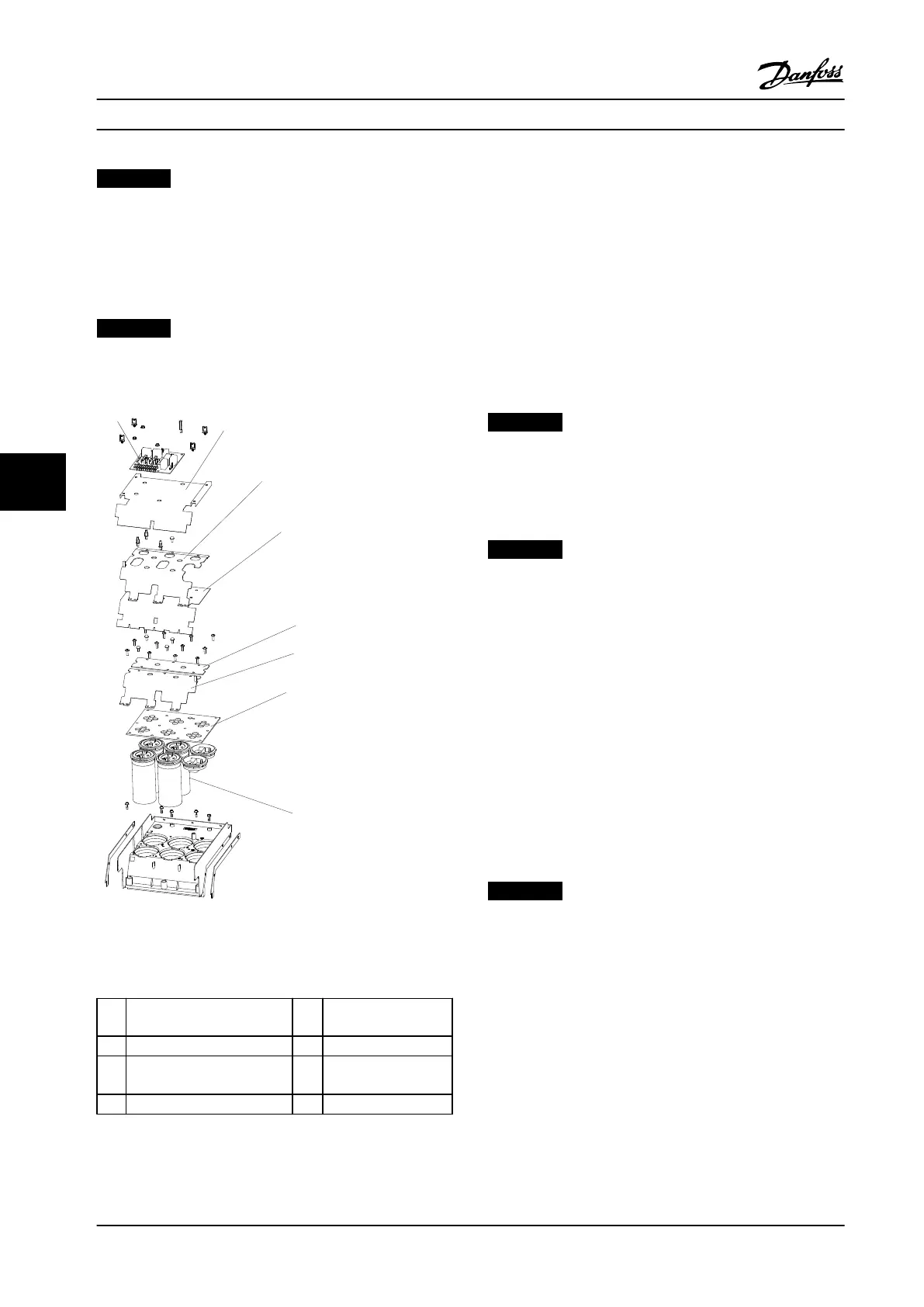
Figure 7.5 Balance/High Frequency Card and DC Capacitor
Bank
400 V unit shown, 690 V units are slightly different.
1
Balance/High frequency card 5 DC center capacitor
plate
2 Capacitor bank cover 6 (+) DC capacitor plate
3 (-) DC capacitor plate 7 Capacitor locking
panel
4 Mylar insulator 8 DC capacitor
Table 7.5 Legend to Figure 7.5
7.3.11.2
690 V AC Power Size
1. Remove the power terminal mounting plate in
accordance with chapter 7.3.8 Power Terminal
Mounting Plate.
2. Unplug the cable MK 100 on the balance/high
frequency card.
3. Remove the one standoff (0.3 in [8 mm]) from the
corner of the card.
4. Remove three nuts (0.3 in [8 mm]).
5. Remove one screw (T20).
NOTICE!
The screw and one of the nuts also hold in place the (+)
DC and (-) DC wire harness.
Reinstall in reverse order of` this procedure and tighten
hardware according to chapter 1.7 General Torque
Tightening Values.
NOTICE!
Note the wire cable connections on the (+) UDC and (-)
UDC terminals.
7.3.12 DC Bus Rails
1. Remove the power card mounting plate in
accordance with chapter 7.3.3 Power Card
Mounting Plate.
2. Remove the power terminal mounting plate in
accordance with chapter 7.3.8 Power Terminal
Mounting Plate.
3. Remove the two screws (T30) at the top end of
the bus bar, one per bus bar.
4. From the other end of the bus bar, remove two
nuts (0.4 in [10 mm]), one per bus bar.
NOTICE!
If there is a brake option, remove the two brake to DC
link bus bars by removing two screws (T30), one per bus
bar and two nuts (0.4 in [10 mm]), one per bus bar.
Reinstall in reverse order of this procedure and tighten
hardware according to chapter 1.7 General Torque
Tightening Values.
Disassembly and Assembly In...
Service Manual
96 Danfoss A/S © Rev. 2014-02-10 All rights reserved. MG94A222
77
 Loading...


