NOTICE!
The adjustable frequency drive is heavy. Removing it
from the options cabinet is a two-person maneuver.
Reinstall in reverse order of this procedure and tighten
hardware according to chapter 1.7 General Torque
Tightening Values.
See Figure 7.28.
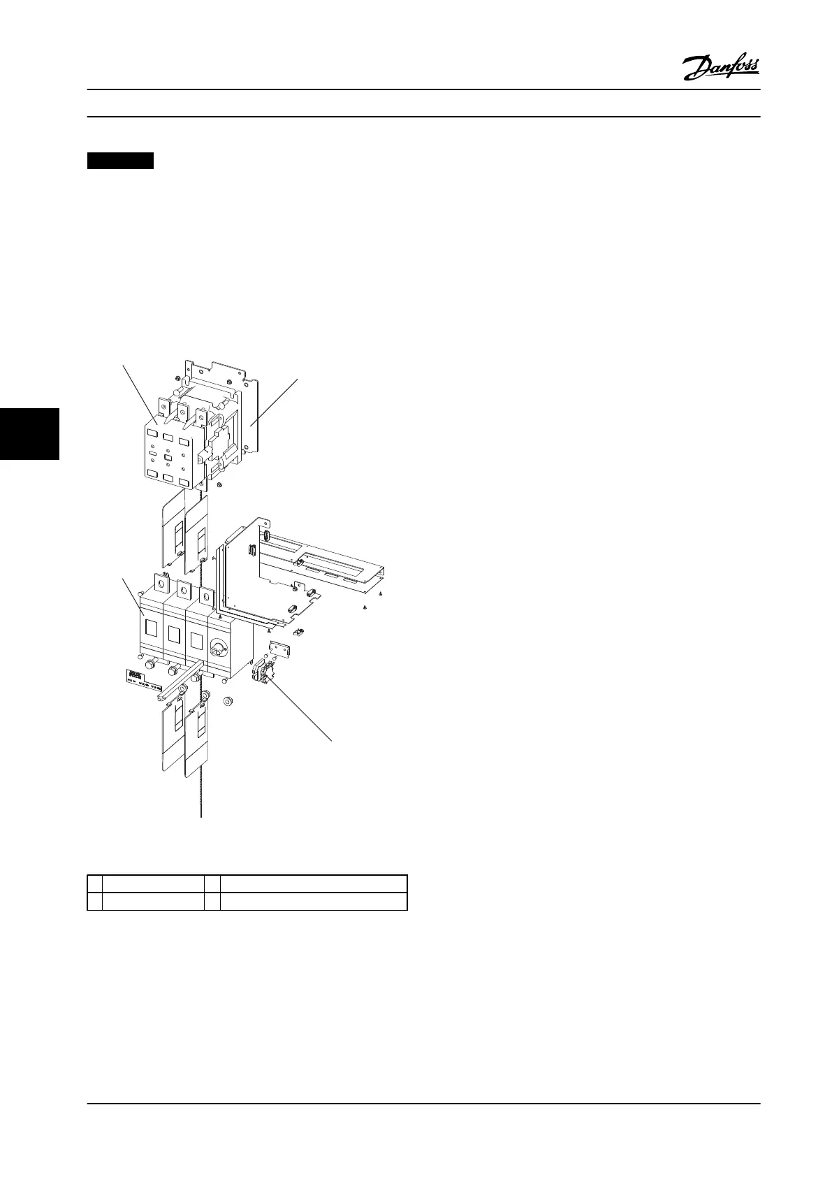
7.6.4 Contactor
Figure 7.29 Contactor and Disconnect
1
Contactor 2 Contactor bracket
3 A1/A2 Terminals 4 Disconnect
Table 7.29 Legend to
1. Remove the input bus bars in accordance with
chapter 7.6.2 Replacing the Heatsink Fan with
Options Cabinet Present.
2. Remove the fuses (not shown) by removing three
nuts (0.7 in [17 mm]) from above the fuses and
three screws (0.7 in [17 mm]) from below the
fuses.
3. Remove the contactor to fuse bus bars by
removing three nuts (0.7 in [17 mm]).
4. Remove the contactor coil wires from terminals
A1 and A2.
5. Remove four bolts (0.5 in [13 mm]) from the
contactor bracket and lift the contactor out.
Reinstall in reverse order of this procedure and tighten
hardware according to chapter 1.7 General Torque
Tightening Values.
7.6.5
Disconnect
1. Remove the fuses in accordance with
chapter 7.6.4 Contactor.
2. Remove four screws (T25), one from each corner
of the disconnect.
3. Remove the disconnect by pulling it downward
and out of the cabinet.
Reinstall in reverse order of this procedure and tighten
hardware according to chapter 1.7 General Torque
Tightening Values
See Figure 7.29.
Disassembly and Assembly In... Service Manual
118 Danfoss A/S © Rev. 2014-02-10 All rights reserved. MG94A222
77
 Loading...


