7.4.20 DC Capacitors
7.4.20.1 400 V AC Power Size
NOTICE!
When performing this procedure, always replace the
entire capacitor bank even if only one capacitor has
failed.
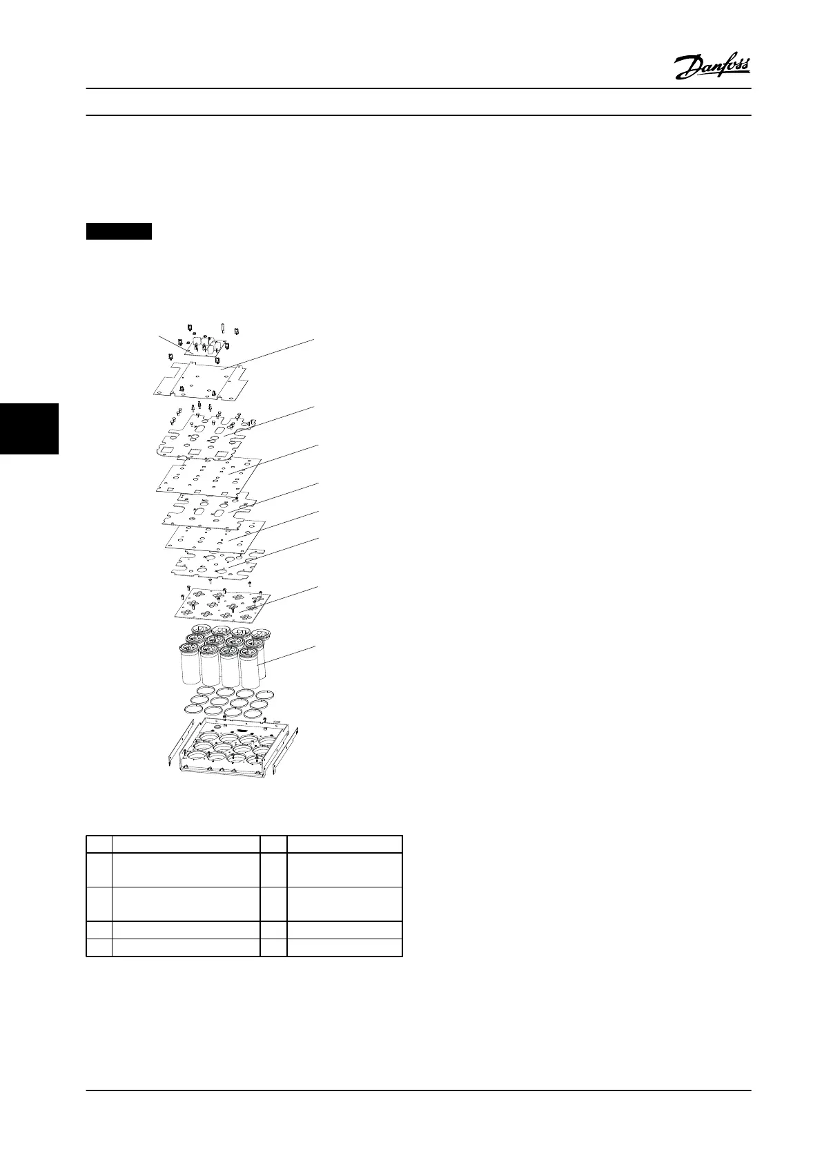
Figure 7.22 DC Capacitors for 400 V AC units
1
Balance/High frequency card 6 Mylar insulator
2 Capacitor bank cover 7 DC center capacitor
plate
3 (+) DC plate 8 Capacitor locking
plate
4 Mylar insulator 9 DC capacitor
5 (-) DC plate
Table 7.22 Legend to Figure 7.22
1. Remove the gate drive card in accordance with
chapter 7.4.14 IGBT Gate Drive Card.
2. Remove the balance/high frequency card in
accordance with chapter 7.4.13 Balance/High
Frequency Card.
3. Remove the DC bus rails in accordance with
chapter 7.4.18 DC Bus Rails.
4. Remove the Mylar cover from the capacitor bank.
5. Remove the IGBT output bus bars by removing
three screws (T20 thread-forming), one per bus
bar, and six screws (T40), two per bus bar.
6. Remove the snubber capacitors, one from each
IGBT module, by removing two screws (T40).
7. Remove the (+)DC plate by removing one
standoff (0.3 in [8 mm]) connecting the plate to
the positive terminal of capacitor 3, and screws
(T25) connecting the plate to the positive
terminals of capacitors 1, 2, 4, 9, and 12. Number
of T25 screws varies based on the size of the
adjustable frequency drive.
8. Remove the insulator between the (+)DC plate
and the (-)DC plate. The screws connecting (-)DC
plate and the DC center plate to the capacitors
may have to be removed to remove the insulator.
9. Remove the (-)DC plate by removing one standoff
(0.3 in [8 mm]) connecting the plate to the
negative terminal of capacitor 6, and screws (T25)
connecting the plate to the negative terminals of
capacitors 5, 7, 8, 10, and 11. Number of T25
screws varies based on the size of the adjustable
frequency drive.
10. Remove the Mylar insulator between the (-)DC
plate and the DC center plate. The screws
connecting the DC center plate to the capacitors
may have to be removed to remove the insulator.
11. Remove the DC center plate by removing:
•
One standoff (0.3 in [8 mm]) connecting
the plate to the negative terminal of
capacitor 2
•
Screws (T25) connecting the plate to the
negative terminal of capacitors 1, 3, 4, 9
and 12
•
Screws (T25) connecting the plate to the
positive terminal of capacitors 5, 6, 7, 8,
10 and 11. Number of T25 screws varies
based on the size of the adjustable
frequency drive
12. Remove the capacitor locking panel by removing
the ten screws (T25 thread-forming).
Disassembly and Assembly In...
Service Manual
112 Danfoss A/S © Rev. 2014-02-10 All rights reserved. MG94A222
77
 Loading...


