130BC506.10
Setup 1
A
B
C
D
5
12
13 14 15
10
11
10
9
6
7
8
4
1
2
3
Menu
Status
Quick
Menu
Main
Menu
Hand
On
O
Reset
Auto
On
Back
OK
On
Warn
Alarm
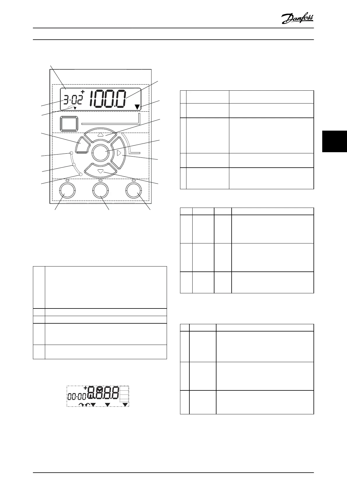
Illustration 5.1 View of the LCP
A. Numeric display
The LCD-display is back-lit with 1 numeric line. All data is
shown in the LCP.
1 The set-up number shows the active set-up and the edit
set-up. If the same set-up acts as both active and edit set-
up, only that set-up number is shown (factory setting).
When active and edit set-up dier, both numbers are
shown in the display (for example, set-up 12). The number
ashing indicates the edit set-up.
2 Parameter number.
3 Parameter value.
4 Motor direction is shown in the bottom left of the display.
A small arrow indicates the direction, either clockwise or
counterclockwise.
5 The triangle indicates whether the LCP is in Status, Quick
Menu, or Main Menu.
Table 5.1 Legend to Illustration 5.1, Section A
130BD135.10
Setup 12
INDEX
AHP
VkW
srpm
Hz%
n2n1
n3
p5 p4
p3 p2 p1
Illustration 5.2 Display Information
B. Menu key
To select between Status, Quick Menu, or Main Menu,
press [Menu].
C. Navigation keys and indicator lights (LEDs)
Key Function
9 [Back] For moving to the previous step or layer
in the navigation structure.
1
0
Arrows [
▲
] [
▼
]
For switching between parameter
groups, parameters, and within
parameters, or increasing/decreasing
parameter values. Arrows can also be
used for setting local reference.
1
1
[OK] Press to access parameter groups or to
enable a selection.
1
2
[►]
Press to move from left to right within
the parameter value to change each
digit individually.
Table 5.2 Legend to Illustration 5.1, Navigation Keys
Indicator Light Function
6 On Green ON turns on when the frequency
converter receives power from the
mains voltage, a DC bus terminal, or a
24 V external supply.
7 Warn Yellow When warning conditions are met, the
yellow WARN light turns on and text
appears in the display area identifying
the problem.
8 Alarm Red A fault condition causes the red alarm
light to ash and an alarm text is
shown.
Table 5.3 Legend to Illustration 5.1, Indicator Lights (LEDs)
D. Operation keys and indicator lights (LEDs)
Key Function
13 Hand On Starts the frequency converter in local control.
•
An external stop signal by control input or
serial communication overrides the local
hand on.
14 O/Reset Stops the motor but does not remove power
to the frequency converter, or resets the
frequency converter manually after a fault has
been cleared.
15 Auto On Puts the system in remote operational mode.
•
Responds to an external start command by
control terminals or serial communication.
Table 5.4 Legend to Illustration 5.1, Section D
Commissioning Operating Instructions
MG07A102 Danfoss A/S © 11/2015 All rights reserved. 21
5 5
 Loading...


