•
Earth ground wire of at least 10 mm
2
•
Two separate earth ground wires both complying
with the dimensioning rules
See EN 60364-5-54 § 543.7 for further information.
Using RCDs
Where residual current devices (RCDs), also known as earth
leakage circuit breakers (ELCBs), are used, comply with the
following:
•
Use RCDs of type B only which are capable of
detecting AC and DC currents
•
Use RCDs with an inrush delay to prevent faults
due to transient earth currents
•
Dimension RCDs according to the system configu-
ration and environmental considerations
3.2.3
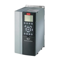
Mains, Motor and Earth Connections
WARNING
INDUCED VOLTAGE!
Run output motor cables from multiple frequency
converters separately. Induced voltage from output motor
cables run together can charge equipment capacitors even
with the equipment turned off and locked out. Failure to
run output motor cables separately could result in death
or serious injury.
Earthing (grounding) clamps are provided for motor wiring
(see Illustration 3.4).
•
Do not install power factor correction capacitors
between the frequency converter and the motor
•
Do not wire a starting or pole-changing device
between the frequency converter and the motor
•
Follow motor manufacturer wiring requirements
•
All frequency converters may be used with an
isolated input source as well as with ground
reference power lines. When supplied from an
isolated mains source (IT mains or floating delta)
or TT/TN-S mains with a grounded leg (grounded
delta), set 14-50 RFI Filter to OFF (size J6-J7) or
remove the RFI screw (J1-J5). When off, the
internal RFI filter capacitors between the chassis
and the intermediate circuit are isolated to avoid
damage to the intermediate circuit and to reduce
earth capacity currents in accordance with IEC
61800-3.
•
Do not install switch between the frequency
converter and the motor in IT mains.
Illustration 3.4 Mains, Motor and Earth Connections
Illustration 3.4 represents mains input, motor, and earth
grounding for basic frequency converters. Actual configu-
rations vary with unit types and optional equipment.
3.2.4
Control Wiring
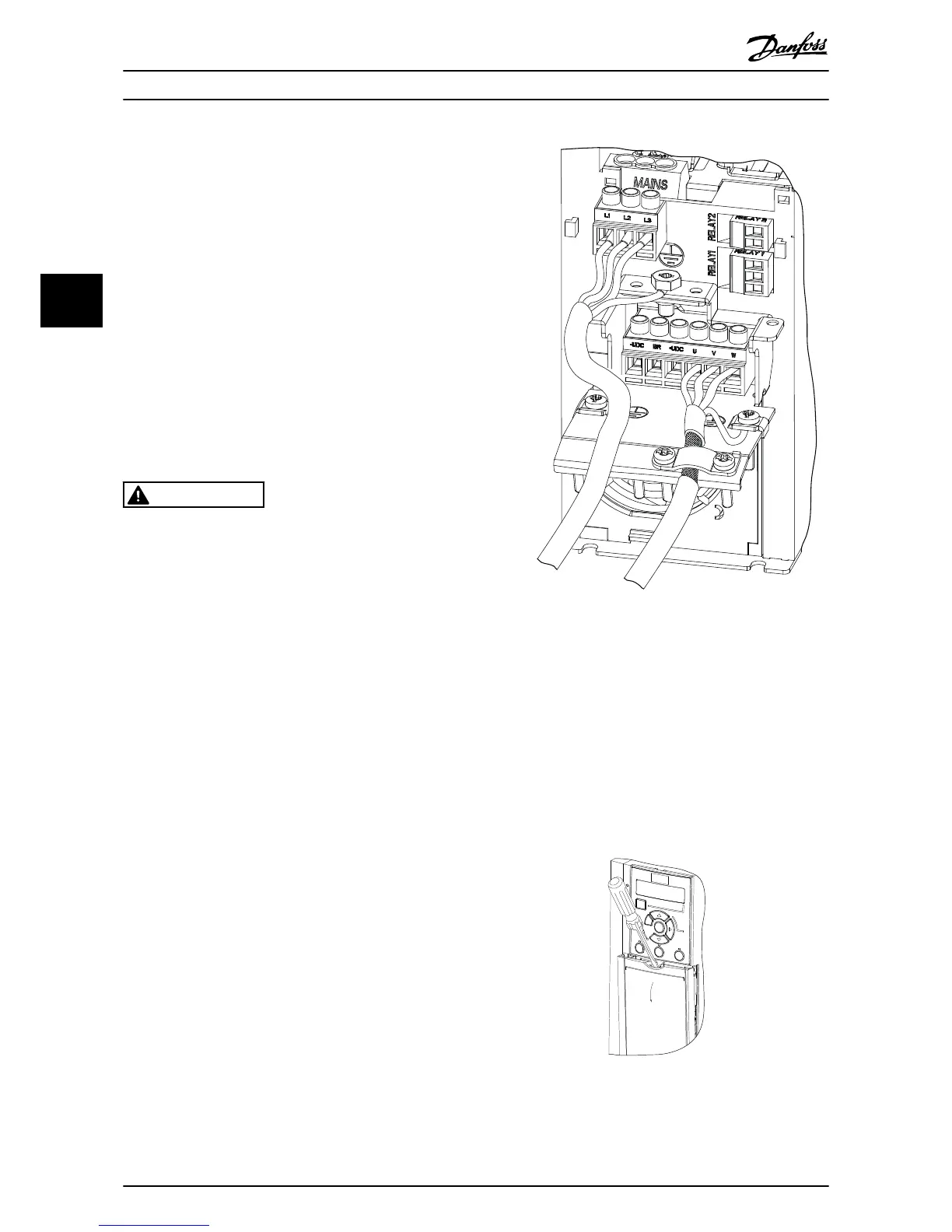
3.2.4.1 Access
•
Remove access cover plate with a screw driver.
See Illustration 3.5.
 Loading...