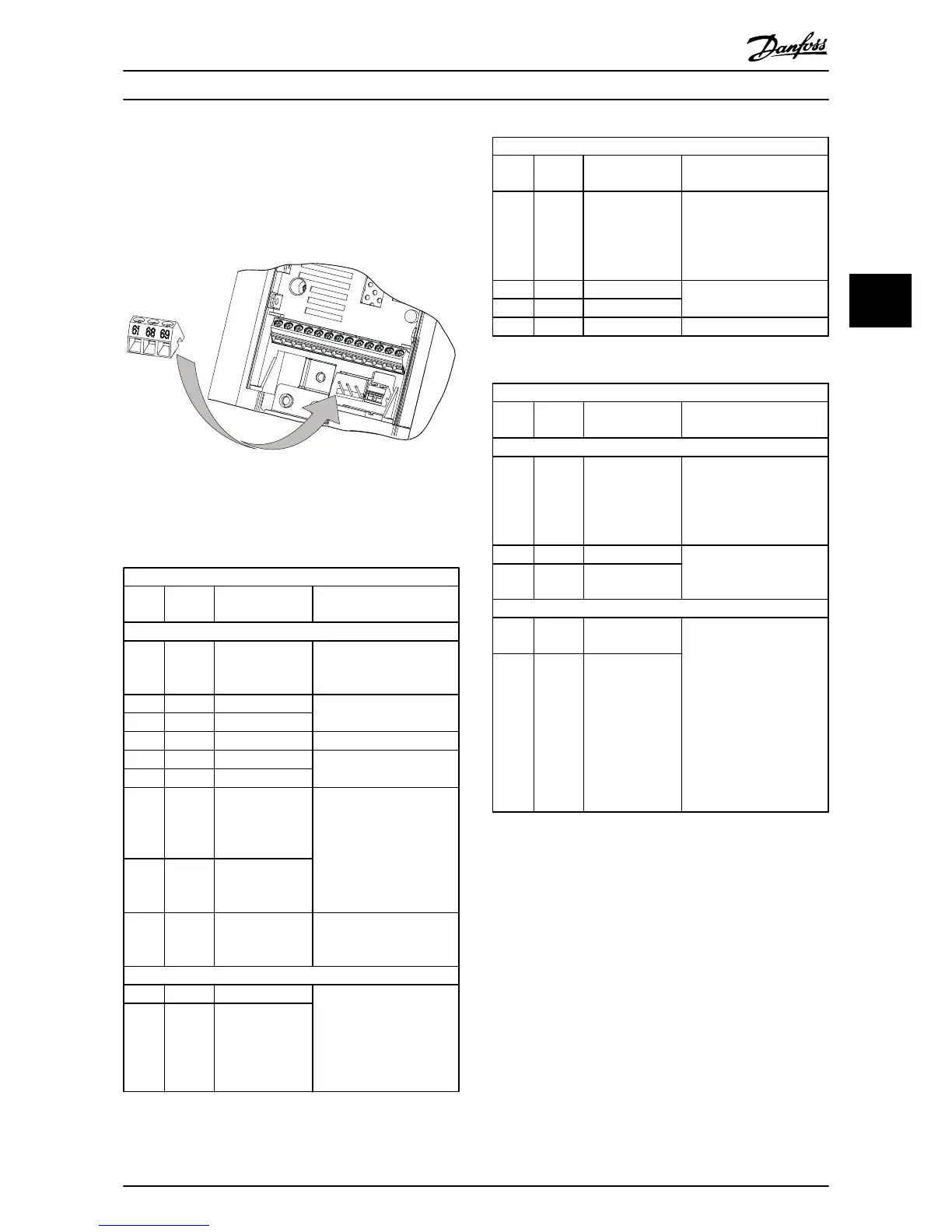
Illustration 3.6 Control Terminal Locations
See 8.2 General Technical Data for terminal ratings details.
Terminal description
Termi
nal
Parame
ter
Default
setting Description
Digital I/O, Pulse I/O, Encoder
12 - +24 V DC 24 V DC supply voltage.
Maximum output current is
100mA for all 24 V loads.
18 5-10 [8] Start
Digital inputs.
19 5-11 [10] Reversing
31 5-16 [0] No operation Digital input, pulse input.
32 5-14 [0] No operation
Digital input, 24 V encoder.
33 5-15 [0] No operation
27 5-12
5-30
DI [2] Coast
inverse
DO [0] No
operation
Selectable for either digital
input, digital output or
pulse output. Default
setting is digital input.
29 5-13
5-31
DI [14] Jog
DO [0] No
operation
20 - Common for digital inputs
and 0V potential for 24V
supply.
Analog inputs/outputs
42 6-91 [0] No operation Programmable analog
output. The analog signal
is 0-20mA or 4-20 mA at a
maximum of 500Ω. Can
also be configured as
digital outputs
45 6-71 [0] No operation
Terminal description
Termi
nal
Parame
ter
Default
setting Description
50 - +10 V DC 10 V DC analog supply
voltage. 15mA maximum
commonly used for
potentiometer or
thermistor.
53 6-1* Reference
Analog input. Selectable
for voltage or current.
54 6-2* Feedback
55 - Common for analog input
Table 3.3
Terminal description
Termi
nal
Parame
ter
Default
setting Description
Serial communication
61 -
Integrated RC-Filter for
cable screen. ONLY for
connecting the screen
when experiencing EMC
problems.
68 (+) 8-3* RS-485 Interface. A control
card switch is provided for
termination resistance.
69 (-) 8-3*
Relays
01, 02,
03 5-40 [0] [0] No operation
Form C relay output. These
relays are in various
locations depending upon
the frequency converter
configuration and size.
Usable for AC or DC
voltage and resistive or
inductive loads.
RO2 in J1-J3 enclosure is 2-
pole, only 04,05 terminal
available
04, 05,
06
5-40 [1] [0] No operation
Table 3.4 Terminal Description
Installation
VLT
®
AutomationDrive FC 360 Quick Guide
MG06A102 - VLT
®
is a registered Danfoss trademark 15
3 3
 Loading...