4 User Interface and Programming
4.1 Programming
4.1.1 Programming with the Numerical
Local Control Panel (NLCP)
The FC 360 supports graphic and numerical local control
panels as well as blind covers. This chapter covers
programming with the NLCP. For programming with the
GLCP, see the VLT
®
Programming Guide, MG06C.
NOTE
The frequency converter can also be programmed from a
PC via RS-485 com-port by installing the MCT-10 Setup
software. This software can either be ordered using code
number 130B1000 or downloaded from the Danfoss Web
site: www.danfoss.com/BusinessAreas/DrivesSolutions/
softwaredownload
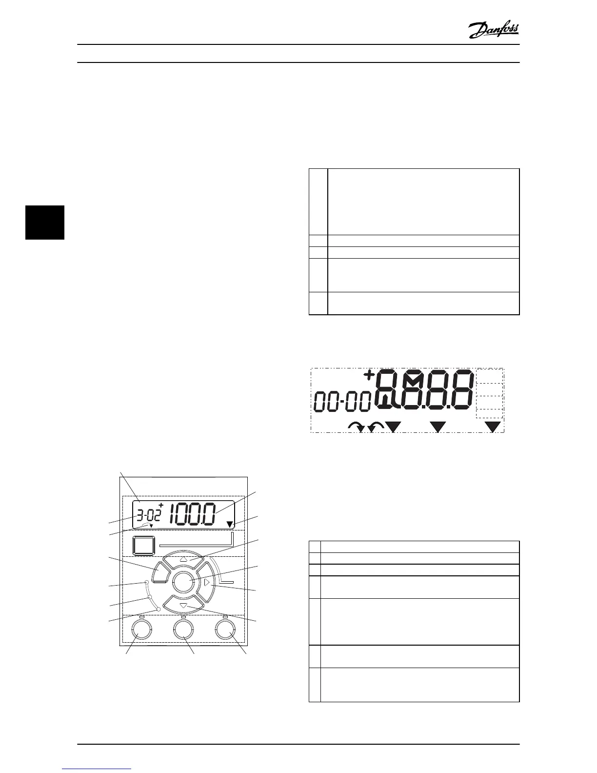
4.1.2 NLCP
The NLCP is divided into four functional sections.
A. Numeric display
B. Menu key
C. Navigation keys and indicator lights (LEDs)
D. Operation keys and indicator lights (LEDs)
130BC506.10
Setup 1
A
B
C
D
5
12
13 14 15
10
11
10
9
6
7
8
4
1
2
3
Menu
Status
Quick
Menu
Main
Menu
Hand
On
O
Reset
Auto
On
Back
OK
On
Warn
Alarm
Illustration 4.1
A. Numeric Display
The LCD-display is back-lit with 1 numeric line. All data is
displayed on the LCP.
1 Set-up number shows the active set-up and the edit set-
up. If the same set-up acts as both active and edit set-up,
only that set-up number is shown (factory setting). When
active and edit set-up differ, both numbers are shown in
the display (Setup 12). The number flashing, indicates the
edit set-up.
2 Parameter number.
3 Parameter value.
4 Motor direction is shown to the bottom left of the display
– indicated by a small arrow pointing either clockwise or
counterclockwise.
5 The triangle indicates if the LCP is in status, quick menu or
main menu.
Table 4.1
130BD135.10
Setup 12
INDEX
AHP
VkW
srpm
Hz%
n2n1
n3
p5 p4
p3 p2 p1
Illustration 4.2 Display Information
B. Menu Key
Use the menu key to select between status, quick menu or
main menu.
C. Navigation keys and indicator lights (LEDs)
6
Green LED/On: Control section is working.
7 Yellow LED/Warn.: Indicates a warning.
8 Flashing Red LED/Alarm: Indicates an alarm.
9 [Back]: For moving to the previous step or layer in the
navigation structure
10
Arrows [
▲
] [
▼
]: For maneuvering between parameter groups,
parameters and within parameters or increasing/decreasing
parameter values. Can also be used for setting local
reference.
11 [OK]: For selecting a parameter and for accepting changes to
parameter settings
12
[►]: For moving from left to right within the parameter value
in order to change each digit individually. See description in
4.1.3 The Right-Key Function.
Table 4.2
User Interface and Programm...
VLT
®
AutomationDrive FC 360 Quick Guide
18 MG06A102 - VLT
®
is a registered Danfoss trademark
44
 Loading...