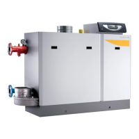
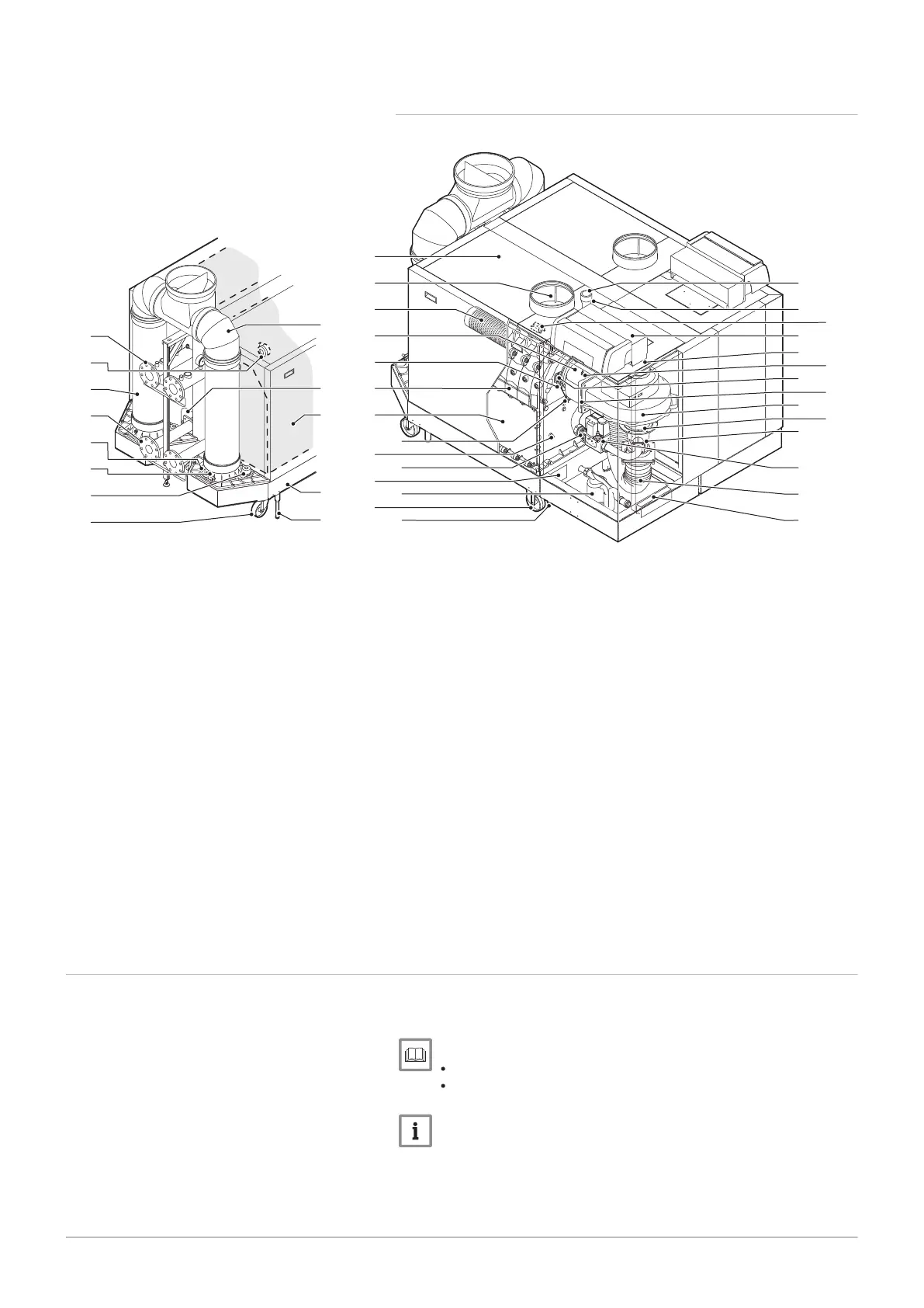
4.3.2 Main components C 630 ECO
Fig.5 C 630 ECO
AD-0000522-01
1
3
4
5
2
6
7
8
27
28
29
30
32
34
31
33
35
36
14
13
15
16
17
18
19
20
22
24
26
21
23
25
10
41
11
12
9
37
38
39
40
1
Flow connection
2
Air pressure differential switch
3
Flue gas outlet
4
Return connection
5
Flue gas measuring point
6
Flue gas thermostat (if present)
7
Condensate collector sealant cap
8
Pivoting castor
9
Adjustment bolt
10
Frame
11
Heat exchanger insulation kit (if present)
12
Flue gas collector
13
Boiler casing
14
Air supply
15
Burner
16
Adapter
17
Ignition/ionisation electrode
18
Heat exchanger
19
Inspection trap
20
Temperature sensor for heat exchanger
21
Return temperature sensor
22
Gas filter
23
Data plate
24
Siphon
25
Transport wheels
26
Adjustment bolt
27
Gas connection
28
Gas pressure measuring point
29
Control panel
30
Installation option for weather-compensated boiler
control
31
Pressure measurement point
32
Flame inspection window
33
Non-return valve
34
Fan
35
Extension piece
36
Venturi
37
Gas valve unit
38
Air supply hose
39
Document holder
40
Ignition transformer
41
Second return connection
4.4
Control panel description
The boiler is supplied with a DIEMATIC iSystem or IniControl control
panel. The control panel is mounted in the boiler.
See
Assembly instructions for the control panel.
Manual for the control panel.
Important
For operation of the C 630 ECO boiler: each module has its own
control panel.
4 Description of the product
7600532 - v.11 - 13122018 21
 Loading...