○ For single-processor systems, sockets A1 to A8 are available.
○ For dual-processor systems, sockets A1 to A8 and sockets B1 to B8 are available.
● In Optimizer Mode, the DRAM controllers operate independently in the 64-bit mode and provide optimized memory
performance.
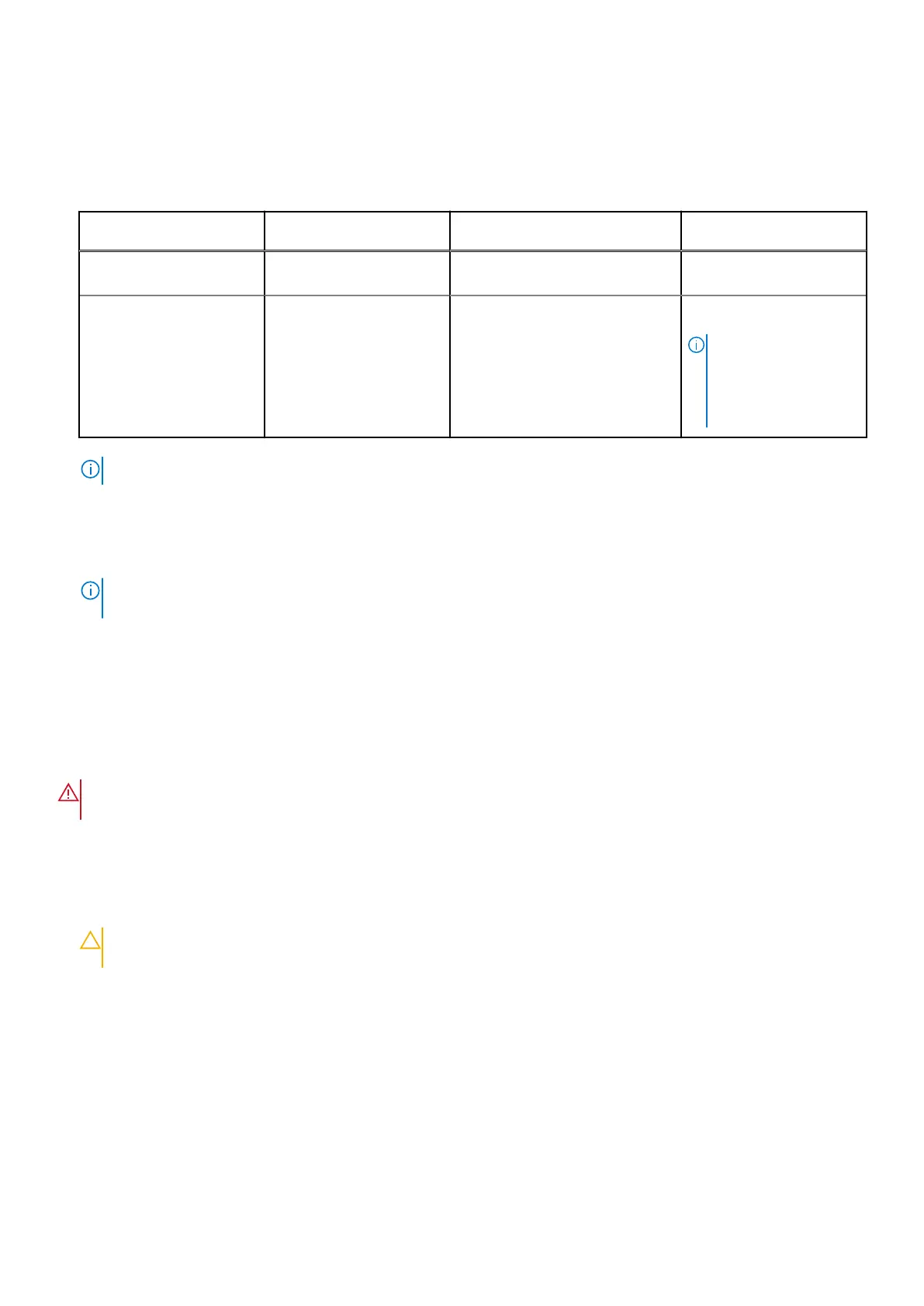
Table 27. Memory population rules
Processor Configuration Memory population Memory population
information
Single processor Optimizer (Independent
channel) population order
A{1}, A{2}, A{3}, A{4}, A{5}, A{6},
A{7}, A{8}
1, 2, 3, 4 DIMMs are
allowed.
Dual processor (Start with
processor1. Processor 1
and processor 2 population
should match)
Optimizer (Independent
channel) population order
A{1}, B{1}, A{2}, B{2}, A{3}, B{3},
A{4}, B{4}, A{5}, B{5}, A{6}, B{6},
A{7}, B{7} A{8}, B{8}
1, 2, 3, 4, 5, 6, 7, 8 DIMMs
are supported per system .
NOTE: Optimizer
population order is not
traditional for 8 and 16
DIMMs installations for
dual processor.
● Memory modules of different capacities can be mixed provided other memory population rules are followed.
NOTE: For example, 8 GB and 16 GB memory modules can be mixed.
● Mixing of more than two memory module capacities in a system is not supported.
● Unbalanced or odd memory configuration results in a performance loss and system may not identify the memory modules
being installed, so always populate memory channels identically with equal DIMMs for best performance.
● Supported RDIMM / LRDIMM configurations are 1, 2, 4, 6, 8 DIMMs per processor.
● Populate eight equal memory modules per processor (one DIMM per channel) at a time to maximize performance.
NOTE:
Equal memory modules refer to DIMMs with identical electrical specification and capacity that may be from
different vendors.
Removing a memory module
Prerequisites
1. Follow the safety guidelines listed in the Safety instructions.
2. Follow the procedure listed in the Before working inside your system.
3. Remove the air shroud.
WARNING:
The memory modules are hot to touch for some time after the system has been powered off. Allow
the memory modules to cool before handling them.
Steps
1. Locate the appropriate memory module socket.
2. To release the memory module from the socket, simultaneously press the ejectors on both ends of the memory module
socket to fully open.
CAUTION:
Handle each memory module only by the card edges, ensuring not to touch the middle of the
memory module or metallic contacts.
3. Lift the memory module away from the system.
70
Installing and removing system components

 Loading...