2. Replace the M2.0 x 2.5 screw to secure the LED board.
3. Connect the LED cable to the LED board.
NOTE: For Latitude 7490, the LED daughter board cable must be routed underneath the securing latch on the palm-
rest, and the label should be placed underneath the system board.
4. Connect the battery cable to the connector on the system board.
5. Install the base cover.
6. Follow the procedure in After working inside your computer.
Smart card module
Removing smart card cage
1. Follow the procedure in Before working inside your computer.
2. Remove the base cover.
3. Disconnect the battery cable from the connector on the system board.
4. Remove the PCIe SSD card.
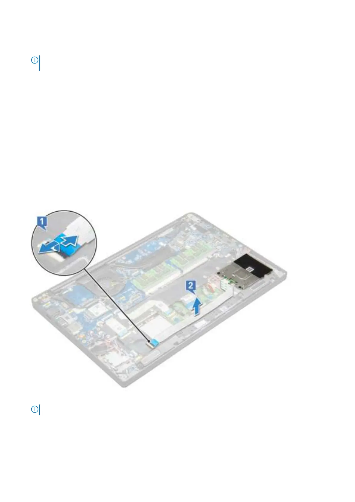
5. To disconnect the smart card cable:
a. Disconnect the smart card cable [1].
b. Lift the smart card cable that is affixed to the touchpad module [2].
6. To remove the smart card cage:
NOTE: To identify the number of screws, see screw list
a. Remove the two (M2.0 x 3.0) screws that secure the smart card cage to the system [1].
b. Slide and lift the smart card cage from the system [2].
26 Removing and installing components
 Loading...