3. Remove the dummy SIM card tray.
4. Remove the base cover.
5. Disconnect the battery cable from the connector on the system board.
6. Remove the memory module.
7. Remove the PCIe SSD.
8. Remove the WLAN card.
9. Remove the WWAN card.
10. Remove the heat sink assembly.
To identify the screws, see
screw list.
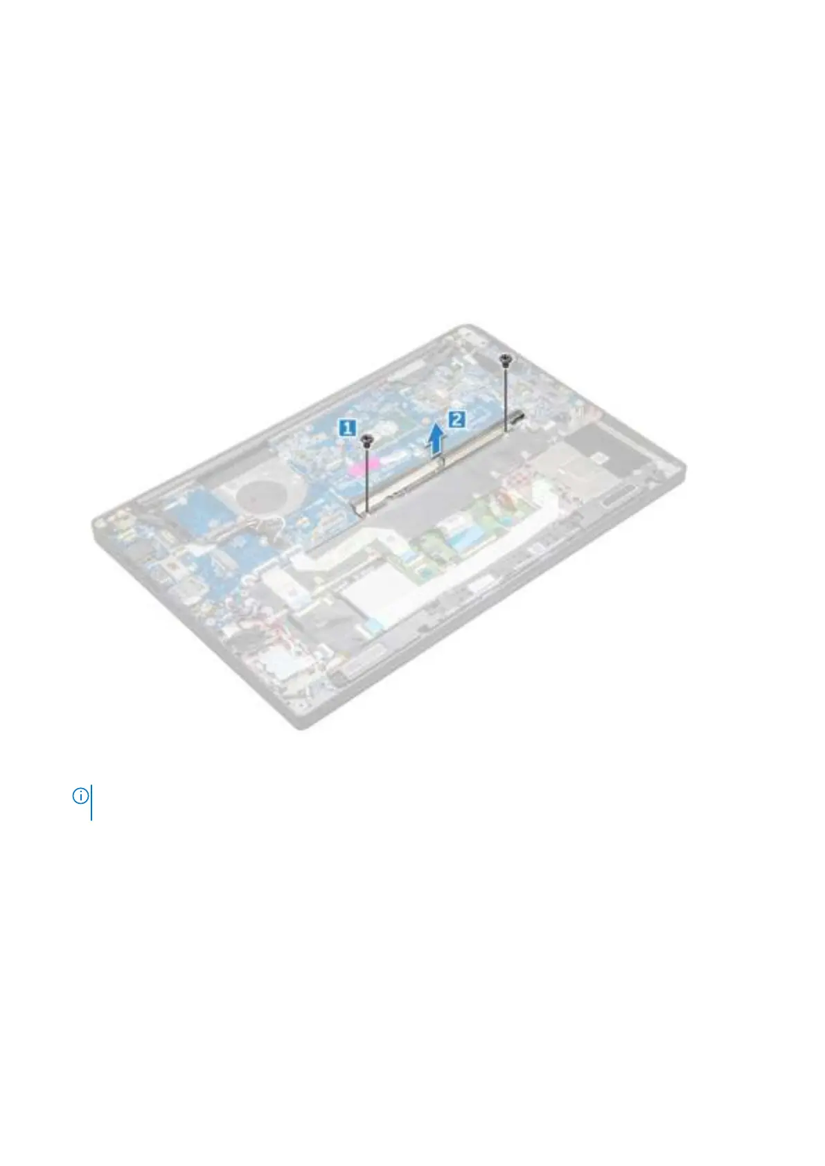
11. To remove the memory module bracket:
a. Remove the two (M2.0 x 3.0) screws that secure memory module bracket to the system board [1].
b. Lift the memory module bracket from the system board [2].
12. To disconnect the eDP cable:display assembly
13. To disconnect the cables:
NOTE: To disconnect the speaker, LED board, coin cell battery, and the power connector port cables, use a plastic
scribe to release the cables from the connectors. Do not pull the cable as it may result in breakage.
a. speaker cable [1]
b. LED board cable [2]
c. coin cell battery cable [3]
d. touchpad cable and USH board cable [4]
e. power connector port [5]
Removing and installing components 41
 Loading...