Item Connector Description
8 NVRAM_CLR System conguration jumper (Retaining or clearing
conguration settings)
9. BOSS/IDSDM IDSDM or BOSS card connector
10. INT_USB1_3.0 Internal USB connector
11. A8, A4, A5, A6, A7, A1, A2, A3 Memory module sockets
12. MEZZ1_FAB_C Mezzanine card connector
13. MEZZ2_FAB_B Mezzanine card connector
14 VFLASH Micro vFlash card connector
15 bNDC Network Daughter Card (NDC) connector
16 CPU1 Processor 1
17 CPU2 Processor 2
18 BATTERY System battery connector
System board jumper settings
For information on resetting the password jumper to disable a password, see Disabling a forgotten password.
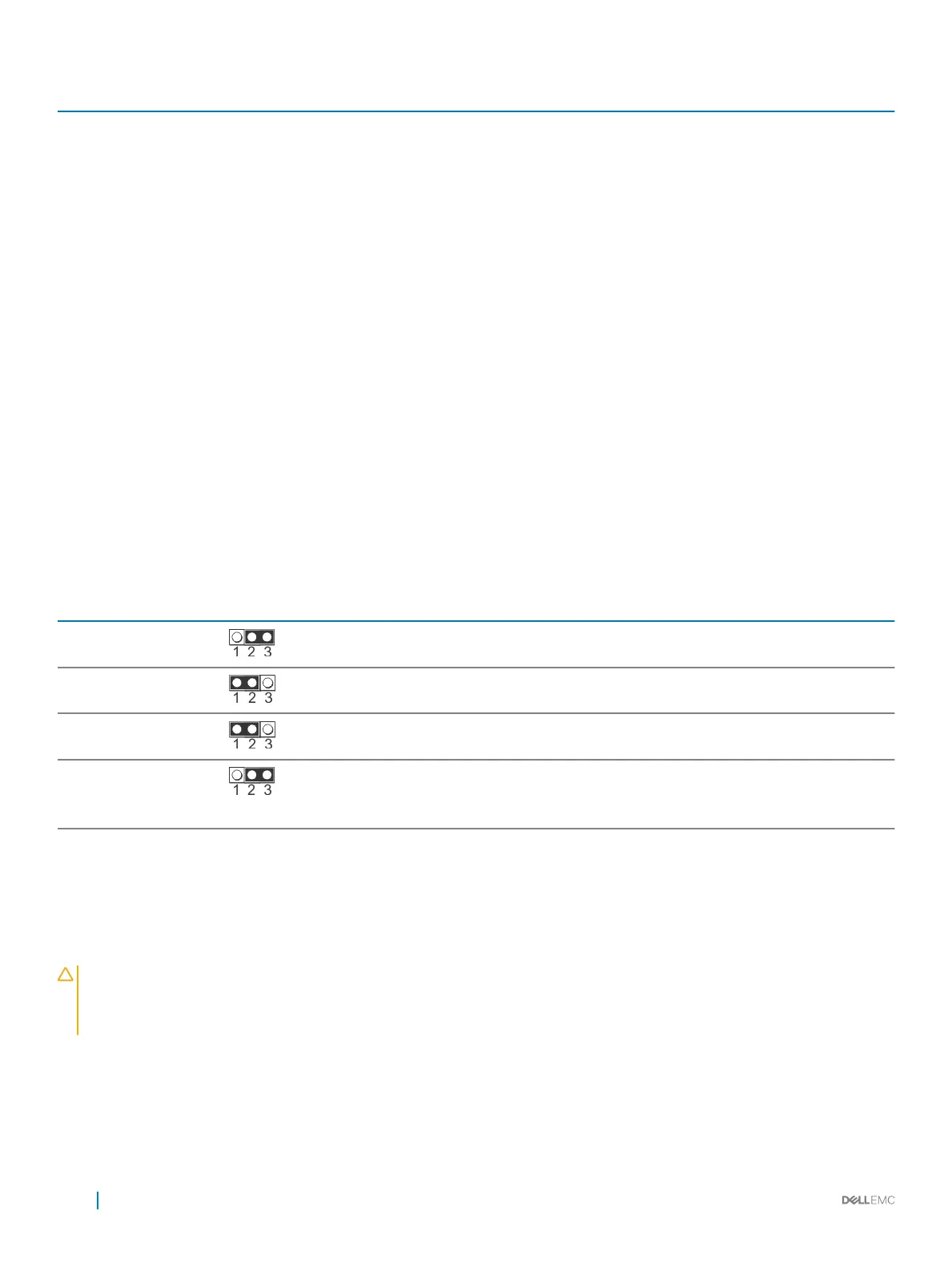
Table 27. System board jumper settings
Jumper Setting Description
NVRAM_CLR
(default)
The BIOS conguration settings are retained at system boot.
The BIOS conguration settings are cleared at system boot.
PWRD_EN
(default)
The BIOS password feature is enabled.
The BIOS password feature is disabled. iDRAC local access is
unlocked at next AC power cycle. iDRAC password reset is enabled
in F2 iDRAC settings menu.
Disabling a forgotten password
The software security features of the PowerEdge FC640 system include a system password and a setup password. The password jumper
enables these password features or disables them, and clears any password(s) currently in use.
Prerequisite
CAUTION
: Many repairs may only be done by a certied service technician. You should only perform troubleshooting and simple
repairs as authorized in your product documentation, or as directed by the online or telephone service and support team. Damage
due to servicing that is not authorized by Dell is not covered by your warranty. Read and follow the safety instructions that came
with the product.
Steps
1 Turn o the system by using the operating system commands or the CMC.
2 Remove the system from the enclosure to access the jumpers.
3 Move the jumper on the system-board jumper from pins 2 and 3 to pins 1 and 2.
4 Install the system in the enclosure.
104
Jumpers and connectors

 Loading...