EasyManuals Logo

Dell PowerEdge T610 User Manual

Dell PowerEdge T610
206 pages
To Next Page IconTo Next Page
To Previous Page IconTo Previous Page
Page #100 background imageLoading...
Page #100 background image
100 Installing System Components
4
Remove the cooling shroud. See "Removing the Cooling Shroud."
5
Disconnect the internal USB module cable from the connector on the
system board, and unroute the cable from the cable guides in the chassis.
See Figure 3-12.
6
Pull up on the module release tab, and slide the internal USB module to
remove it from the slots in the chassis. See Figure 3-12.
7
Install the cooling shroud. See "Installing the Cooling Shroud."
8
Install the expansion card stabilizer. See "Installing the Expansion Card
Stabilizer."
9
Close the system. See "Closing the System."
10
Place the system upright and on its feet on a flat, stable surface.
11
Reattach any peripherals, then connect the system to the electrical outlet.
12
Turn on the system and attached peripherals.
book.book Page 100 Tuesday, September 15, 2009 10:08 AM

Table of Contents

Other manuals for Dell PowerEdge T610

Questions and Answers:

Question and Answer IconNeed help?

Do you have a question about the Dell PowerEdge T610 and is the answer not in the manual?
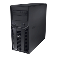
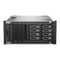
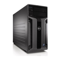
Dell PowerEdge T610 Specifications

General IconGeneral
Form Factor5U Tower
ChipsetIntel 5520
Memory Slots12 DIMM slots
ProcessorUp to two Intel Xeon 5500 or 5600 series processors
Memory1GB/2GB/4GB/8GB/16GB DDR3
Drive BaysUp to 8 x 3.5" or 16 x 2.5" hot-swap SAS, SATA or SSD
RAID ControllerPERC 6/i, PERC H700, PERC H800
Power Supply570W or 870W
Network InterfaceEmbedded Broadcom NetXtreme II 5709c Gigabit Ethernet
Maximum Internal StorageUp to 16TB
Expansion Slots6 PCIe slots
Operating System SupportMicrosoft Windows Server, Red Hat Enterprise Linux, SUSE Linux Enterprise Server, VMware

Related product manuals