Installing System Components 151
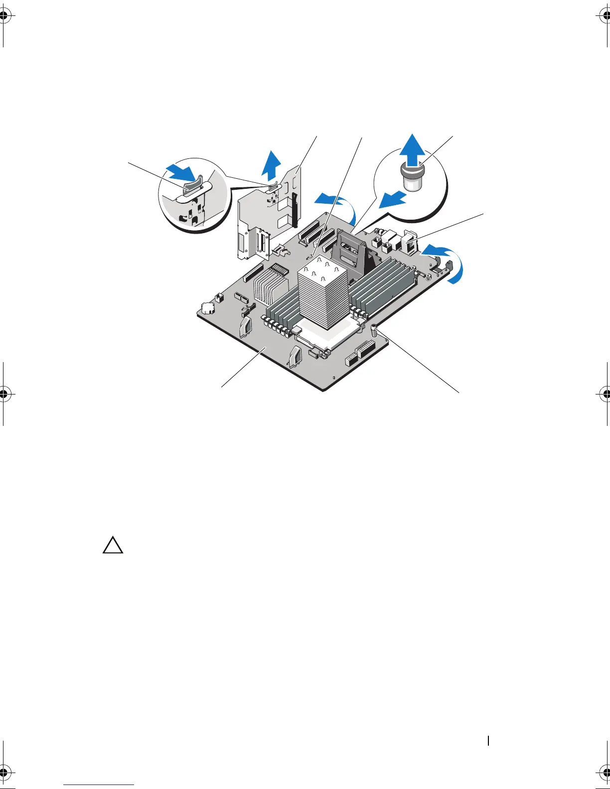
Figure 3-27. Removing and Installing the System Board
Installing the System Board
CAUTION: Many repairs may only be done by a certified service technician. You
should only perform troubleshooting and simple repairs as authorized in your
product documentation, or as directed by the online or telephone service and
support team. Damage due to servicing that is not authorized by Dell is not covered
by your warranty. Read and follow the safety instructions that came with the
product.
1
Unpack the new system board and remove the label placard that is inserted
in the memory module socket.
2
Remove the front bezel. See "Removing the Front Bezel."
1 release latch 2 expansion card stabilizer bracket
3 system board securing slot 4 system board release pin
5 system board connectors 6 system board touch point (2)
7 system board
book.book Page 151 Tuesday, September 15, 2009 10:08 AM
 Loading...