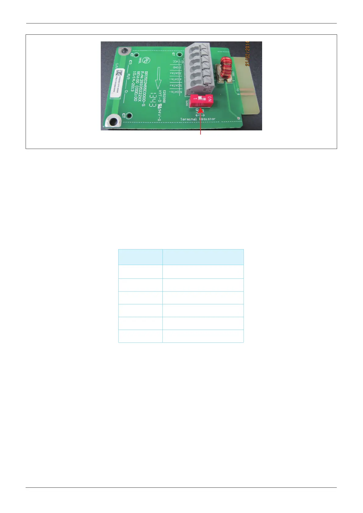
Terminal resistor switch
Figure 5-5: Communication module
Table 5-5: Definition of RS485
5.4.1 RS-485 Connection
The pin definition of RS-485 shown in Table 5-5 and protocol settings are listed in
Table 5-6. Installer must switch the terminal resistor switch to ON when only a single
inverter is installed. The wiring of multi-inverter is shown in Figure 5-6. The terminal
resistor switch of the first and last inverters should be switched ON, and the others OFF.
PIN
FUNCTION
1
VCC
2
GND
3
4
5
6
DATA+
DATA
-
DATA+
DATA
-
22
Wiring
 Loading...


