Chapter 5 Control Terminals | VFD-ED
5-3 Control Circuit Terminals
Terminals Terminal Function Default (NPN mode)
+24 V /
E24 V
Digital control signal common
terminal (Source)
+24V ± 5% 200 mA
COM
Digital control signal common
terminal (Sink)
Common terminal for multi-function input terminals
FWD Forward-Stop command
FWD-DCM:
ON = run in forward
OFF = decelerate to stop
REV Reverse-Stop command
REV-DCM:
ON = run in reverse
OFF = decelerate to stop
MI1
–
MI8
Multi-function input 1–8
Refer to parameters Pr.02-01–Pr.02-
the multi-function inputs MI1–MI8.
Source mode:
Rated load: 24 V
DC
/ 9.6 mA
Source Mode (PNP)
N.O. (ON, 1): ≥ 17 V
DC
N.C. (OFF, 0): ≤ 5 V
DC
Sink Mode (NPN)
N.O. (ON, 1): ≤ 7 V
DC
N.C. (OFF, 0): ≥ 19 V
DC
DCM
Digital frequency signal common
terminal
SCM1
The default is short-circuited (E24V/STO1/STO2).
The default is short-circuited (SCM1/SCM2/DCM).
Power cutoff safety function for EN954-1 and IEC/EN61508.
When STO1–SCM1 and STO2–SCM2 are ON, the activation current is 3.3 mA ≥ 11 V
DC
.
SCM2
STO1
STO2
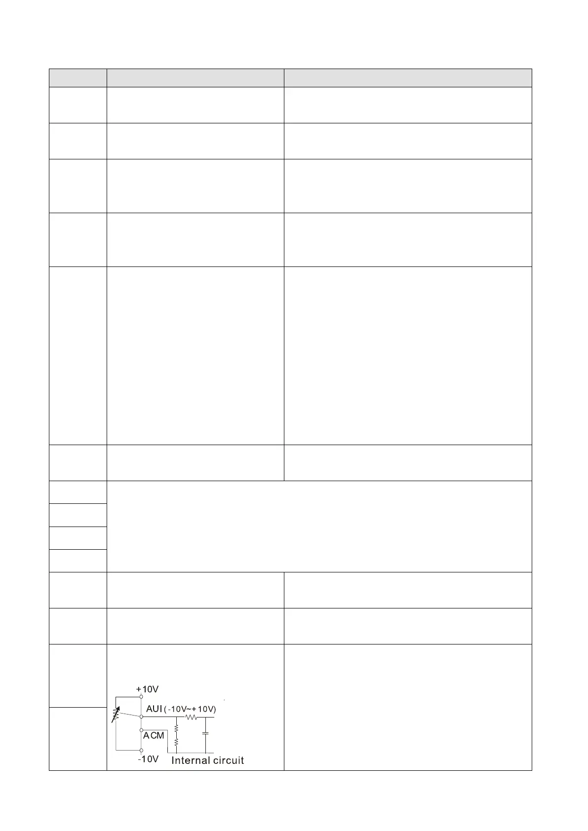
+10 V Potentiometer power supply
Power supply for analog frequency setting: +10 V
DC
20 mA
-10 V Potentiometer power supply
Power supply for analog frequency setting: -10 V
DC
20 mA
AUI1
Analog voltage frequency
command
Impedance: 20 kΩ
Range: -10–10 V
DC
= 0–Maximum Output
Frequency (Pr.01-00)
AUI2
 Loading...