EasyManua.ls Logo

Delta VFD-EL-W Series User Manual

Delta VFD-EL-W Series
217 pages
To Next Page IconTo Next Page
To Previous Page IconTo Previous Page
Page #137 background imageLoading...
Page #137 background image
Chapter 4 ParametersVFD-EL-W
132
<7E1>=1AH
<7O1>=0AH
<8N2>=07H
<8E1>=1BH
<8O1>=0BH
*/
for(i=0;i<=16;i++){
while(!(inportb(PORT+LSR) & 0x20)); /* wait until THR empty */
outportb(PORT+THRtdat[i]); /* send data to THR */ }
i=0;
while(!kbhit()){
if(inportb(PORT+LSR) & 0x01){ /* b0==1read data ready */
rdat[i++]=inportb(PORT+RDR); /* read data form RDR */
} } }
09.05
Reserved
09.06
Reserved
09.07
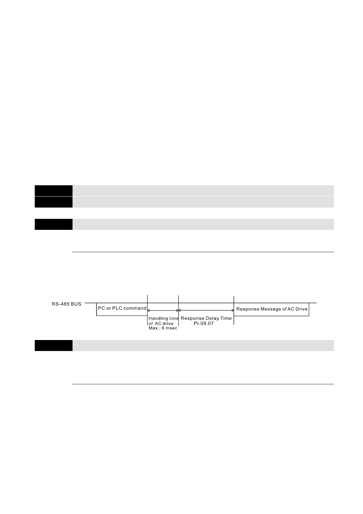
Communication Response Delay Time
Default: 1
Settings
0–200 (unit: 2ms)
If the host controller does not finish the transmitting/receiving process, you can use this
parameter to set the response delay time after the AC motor drive receives communication
command as shown in the following picture.
09.08
Communication Keypad Selection
Default: 0
Settings
0: PU06
1: PU08
After changing the communication method, you need to power off and reboot the drive, or
unplug the keypad and plug it in again to establish new communication.

Other manuals for Delta VFD-EL-W Series

Question and Answer IconNeed help?

Do you have a question about the Delta VFD-EL-W Series and is the answer not in the manual?

Delta VFD-EL-W Series Specifications

General IconGeneral
BrandDelta
ModelVFD-EL-W Series
CategoryDC Drives
LanguageEnglish

Summary

Delta Sensorless Vector Control Compact Drive VFD-EL-W Series

Safety Precautions Before Installation

Disconnect AC Input Power

Safety precaution: Always disconnect AC input power before wiring.

Capacitor Charge Warning

Safety precaution: DC-link capacitors may retain hazardous voltage even after power is off.

Static Sensitive Components

Safety precaution: MOS components are sensitive to static electricity; use anti-static measures.

No Internal Modifications

Safety precaution: Do not modify internal components or wiring of the AC motor drive.

Proper Grounding

Safety precaution: Ensure proper grounding of the AC motor drive using the ground terminal.

Installation Location Restrictions

Safety precaution: Avoid installing the drive in high temperature or flammable environments.

Chapter 2: Installation and Wiring

Chapter 3: Keypad and Start-up

Operation Method Selection

Selection of operation modes: communication, digital keypad, or external signals.

Trial Run Procedure

Procedure for performing a trial run, including checks and motor rotation direction.

Chapter 4: Parameters

Operation Method Parameters

Parameters for selecting frequency command sources and operation command sources.

Protection Parameters

Parameters for over-voltage, over-current stall prevention, and over-torque detection.

Motor Parameters

Parameters for setting motor rated current, no-load current, auto-torque compensation, and auto-tuning.

Communication Parameters

Parameters for communication address, transmission speed, fault treatment, and protocol selection.

PID Control Parameters

Parameters for PID set point selection, input terminals, and proportional/integral/differential gains.

Parameter Settings for Applications

Application-specific parameter settings for speed search, DC brake, energy saving, and multi-step speed.

Chapter 5: Troubleshooting

Over-Current (oc) Troubleshooting

Flowchart for troubleshooting over-current faults, including checks for short circuits and load.

Over-Voltage (ov) Troubleshooting

Flowchart for troubleshooting over-voltage faults, including checks for deceleration time and brake units.

Low Voltage (Lv) Troubleshooting

Flowchart for troubleshooting low voltage faults, including power supply and component checks.

Overheat (oH1) Troubleshooting

Flowchart for troubleshooting overheat faults, including checks for load, fans, and ambient temperature.

Overload (oL) Troubleshooting

Flowchart for troubleshooting overload faults, including checks for settings and load.

Motor Does Not Run Diagnosis

Comprehensive flowchart for diagnosing why the motor does not run, covering various checks.

Chapter 6: Fault Code Information and Maintenance

Fault Code Information

Displays fault names, descriptions, and corrective actions for common faults like Over-current and Over-voltage.

Resetting the Drive After Fault

Instructions on how to reset the drive after a fault, using the RESET key or communication.

Appendix C: Selecting the Right AC Motor Drive

Capacity Formulas for Motor Selection

Formulas for calculating starting capacity and current for single and multiple motor drives.

Related product manuals