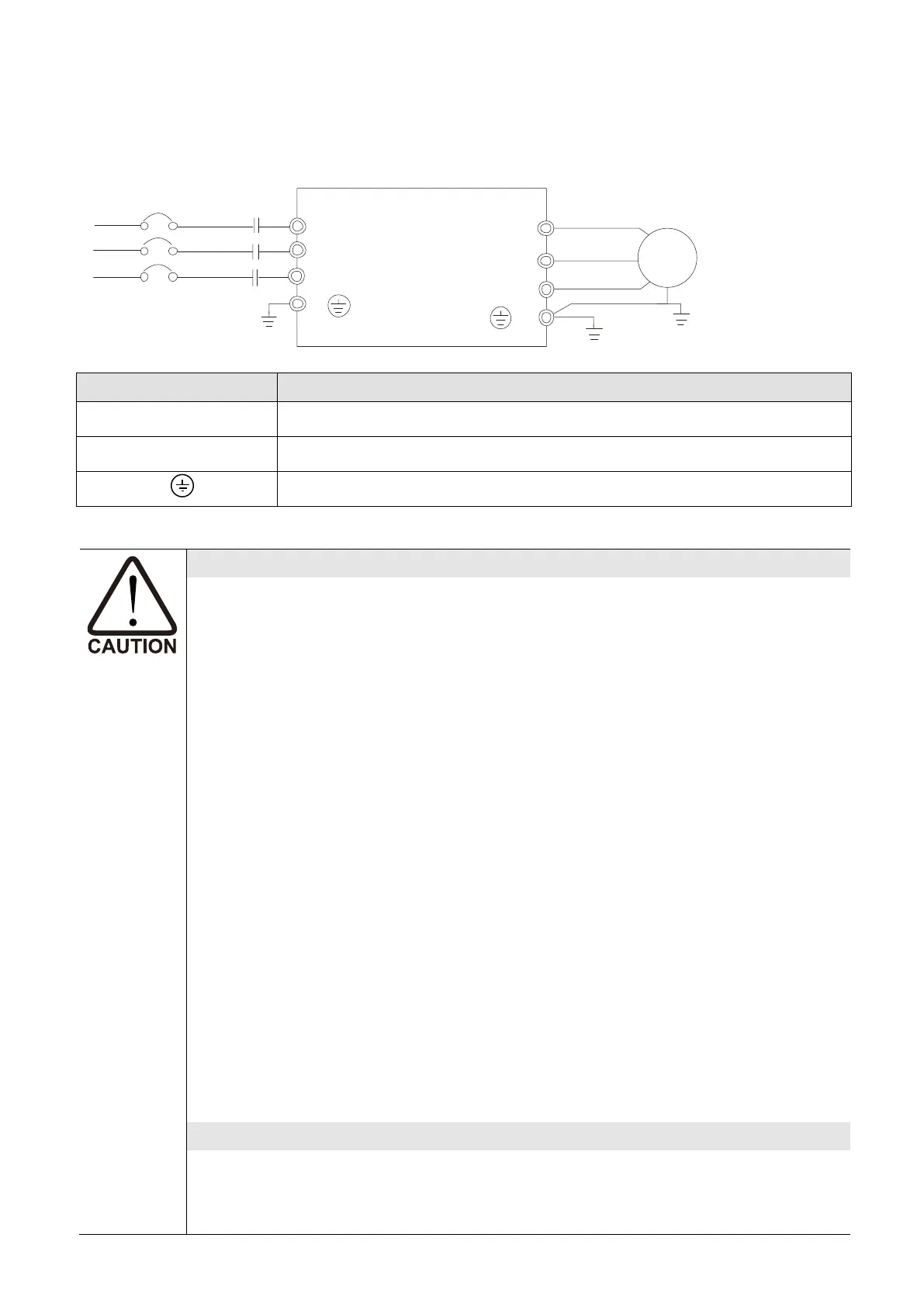
Mains power terminals (R/L1, S/L2, T/L3)
Do NOT connect three-phase motor drives to single-phase AC power. There is no
sequential order when connecting mains power terminals R/L1, S/L2, T/L3.
Connect these terminals with a freely usable standard.
Connect terminals (R/L1, S/L2, and T/L3) with a non-fuse breaker to three-phase
AC power for circuit protection. It is recommended that you add a magnetic
contactor (MC) in the power input wiring to cut off power quickly and reduce
malfunction when activating the protection function for the AC motor drives. Both
ends of the MC should have an R-C surge absorber.
Make sure that you correctly tighten the main circuit terminal screws to prevent
sparks caused by loosening screws due to vibration.
Use voltage and current levels according to the specifications in Appendix A.
When using a GFCI (Ground Fault Circuit Interrupter), select a current sensor with
sensitivity of 200 mA or higher, and not less than 0.1 second operation time to
avoid nuisance tripping. For specific GFCI of the AC motor drive, select a current
sensor with sensitivity of 30 mA or higher.
Do NOT run or stop AC motor drives by turning the power ON or OFF. Use the
RUN or STOP command through the control terminals or a keypad. If you still
need to run or stop the AC drives by turning the power ON or OFF, it is
recommended to do so no more often than ONCE per hour.
Output terminals for main circuit (U, V, W)
The default for the operation direction is running forward. The method to control
the running direction is to set by the communication parameters. Refer to the
Parameter Group 09 in Chapter 4 for details.
 Loading...