Chapter 4 Parameters|VFD-EL-W
145
4-4 Adjustment and Application
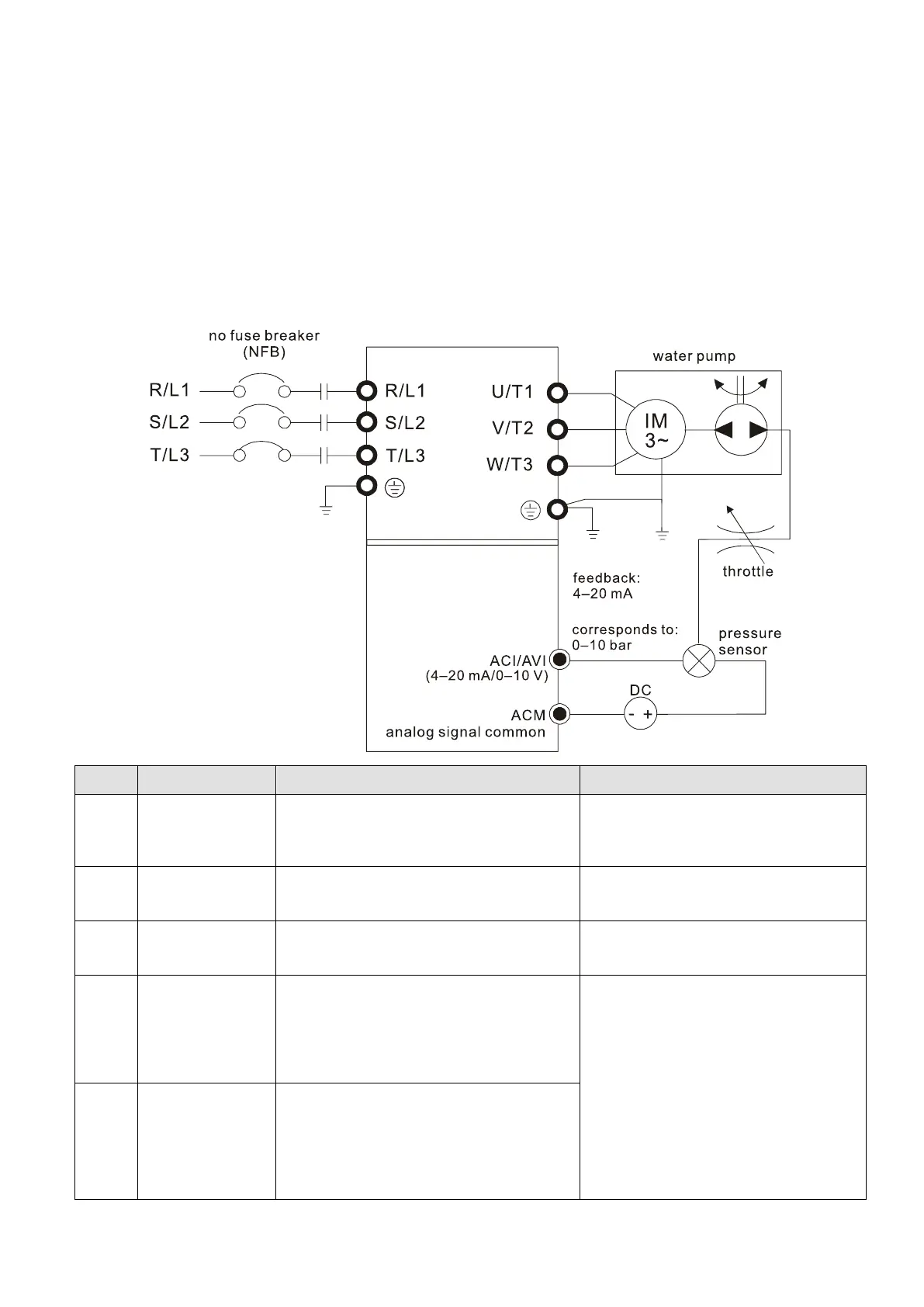
Using PID control in a constant pressure pump feedback application:
Set the application constant pressure value (bar) as PID set point. The pressure sensor sends the actual
value as the PID feedback value. After comparing the PID set point and PID feedback, an error displays.
The PID controller calculates the output by using proportional gain (P), integral time (I) and differential
time (D) to control the pump. It controls the drive to use a different pump speed and achieves constant
pressure control.
The general pressure measuring range of the pressure sensor is 0–10 bar, correspond to 4–20 mA
as the drive feedback signal.
Pressure conversion relation: 0.1 Mpa = 1 bar = 1 kgf-cm
2
Pr.10.00 PID Set Point Selection
Pr.10.01 Input Terminal for PID Feedback
Multi-pump system: the pressure
feedback signal only connects to the
Master pump, so set the PID for the
master pump only.
Pr.10.02 (P)
Pr.10.03 (I)
Pr.10.04 (D)
Multi-pump system: Each drive has a
PID controller. Set the parameters for
all drives.
Acceleration and
deceleration
setting
Pr.01.09 Acceleration Time 1
Pr.01.10 Deceleration Time 1
Multi-pump system: set the
acceleration and deceleration time for
each drive
Keypad multi-
function display
Pr.00.04 Content of Multi-function Display
(User-Defined)
5 (Display PID analog feedback signal
(b))
8 (Display the setting values for PID
control and feedback signal)
1. The VFD-EL-W keypad displays the
PID setting and physical quantity
feedback values. Refer to the
following description for parameters
settings.
2. Multi-pump system: set the above
related parameters of keypad for
each drive.
Correspondence
setting of
frequency and
physical quantity
Pr.00.13 User-defined value
Pr.00.14 Decimal Places for User-
Defined Value
Pr.10.18 PID Feedback Physical Quantity
 Loading...