EasyManuals Logo
Home>Delta>DC Drives>VFD-EL-W Series

Delta VFD-EL-W Series User Manual

Delta VFD-EL-W Series
217 pages
To Next Page IconTo Next Page
To Previous Page IconTo Previous Page
Page #138 background imageLoading...
Page #138 background image
Chapter 4 ParametersVFD-EL-W
133
10 PID Control Parameters
You can set this parameter during operation.
10.00
PID Set Point Selection
Default: 0
Settings
0: PID function disabled
1: Digital keypad
2: Reserved
3: Reserved
4: PID reference target value (Pr.10.11)
Set Pr.00.03 = 3 and 00.04 = 8 for feedback value to display the PID set point on the control
panel at the same time.
When Pr.10.00 is set to 1 and operated by the keypad, adjust the set point by pressing the
up/down keys directly on any display interface if you need to set the set point.
When Pr.10.00 is set to 4, the setting range of Pr.10.11 is limited by the maximum operating
frequency of Pr.01.00. The maximum frequency value of 01.00 is the maximum value of the
physical quantity to the set point corresponds to the maximum range of the physical quantity
measured by the sensor (set in Pr.10.18).
If the set and displayed target value directly correspond to physical quantities such as pressure,
temperature, flow, etc., you also need to set Pr.00.13 and Pr.00.14 at the same time. For
example, when the maximum range of the set point set as 16.0 bar, you also need to set
Pr.00.13 = 160, 00.14 = 1.
The target physical quantity corresponding to the frequency set by Pr.10.11 = (Pr.10.11/
Pr.01.00) × Pr.00.13 × 10
-(Pr.00.14)
. For example, Pr.10.11 = 20 Hz, Pr.01.00 = 50 Hz, Pr.00.13 =
160, Pr.00.14 = 1, then the target physical quantity = 20 / 50 × 160 × 0.1 = 8.0.
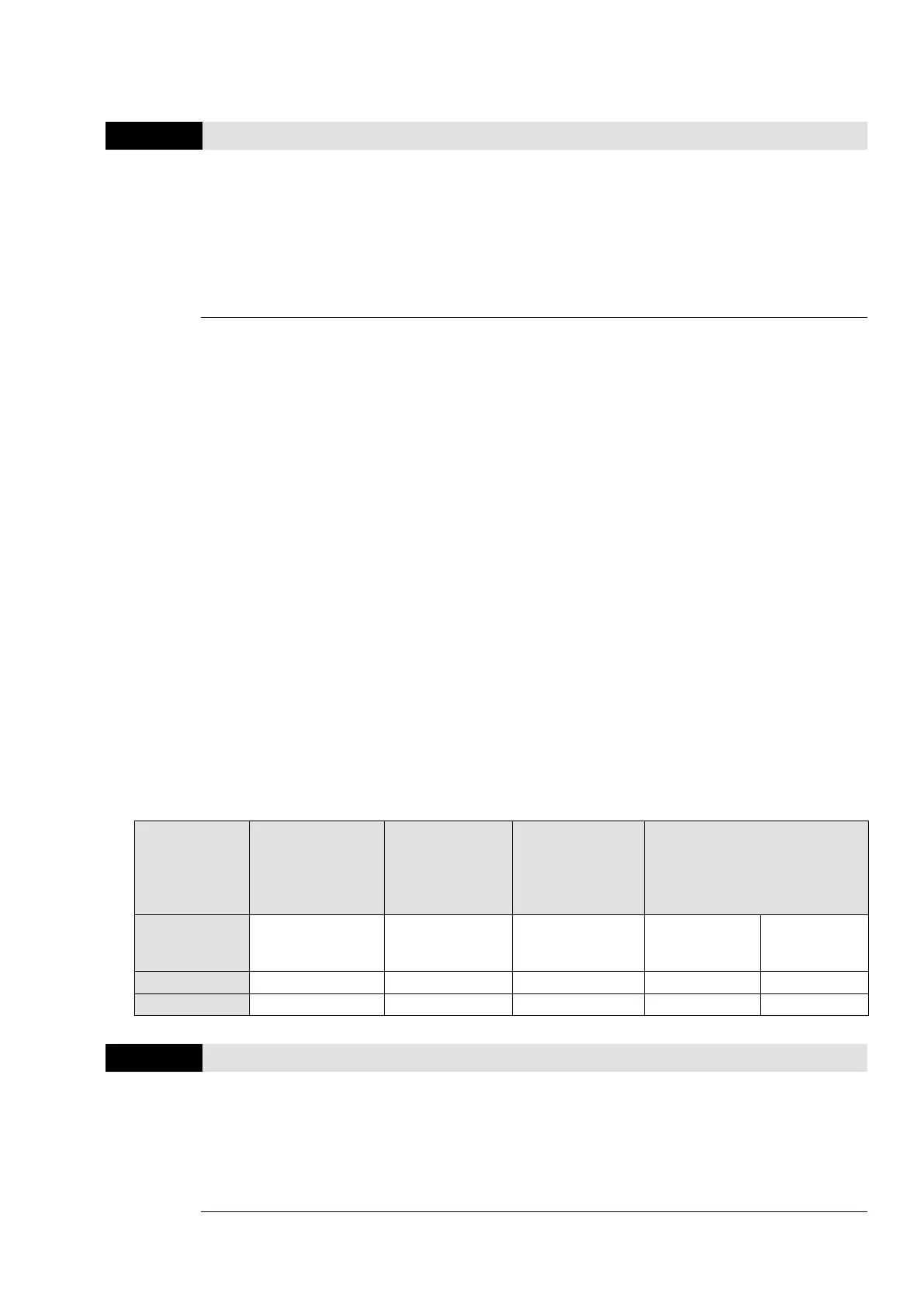
The following table shows the set point physical quantity and the operating frequency of the
drive, sensor feedback value correspond to the physical quantity, set point setting method and
relationship.
Corresponded
Relation
Set Point
Physical
Quantity
Corresponded
Drive Operation
Frequency
Sensor Feed
Value
Corresponding
to the Physical
Quantity
PID Set Point
Parameter
Setting
Pr.00.13 = 160
Pr.00.14 = 1
Pr.00.02 = 9
Pr.01.00 = 50
Pr.10.18 = 16.0
Pr.10.00 = 1
Keypad
up/down keys
Pr.10.00 = 4
Pr.10.11 = 50
Lower Limit
0
0
0
0
0
Upper Limit
16.0
50
16.0
16.0
16.0
10.01
Input Terminal for PID Feedback
Default: 0
Settings
0: Positive PID feedback from external terminal AVI (010 V
DC
)
1: Negative PID feedback from external terminal AVI (010 V
DC
)
2: Positive PID feedback from external terminal ACI (420 mA)
3: Negative PID feedback from external terminal ACI (420 mA)
Select the input terminal as the PID detection terminal, and note that the master frequency

Other manuals for Delta VFD-EL-W Series

Questions and Answers:

Question and Answer IconNeed help?

Do you have a question about the Delta VFD-EL-W Series and is the answer not in the manual?

Delta VFD-EL-W Series Specifications

General IconGeneral
BrandDelta
ModelVFD-EL-W Series
CategoryDC Drives
LanguageEnglish

Related product manuals