Chapter 2 Installation and WiringVFD-EL-W
25
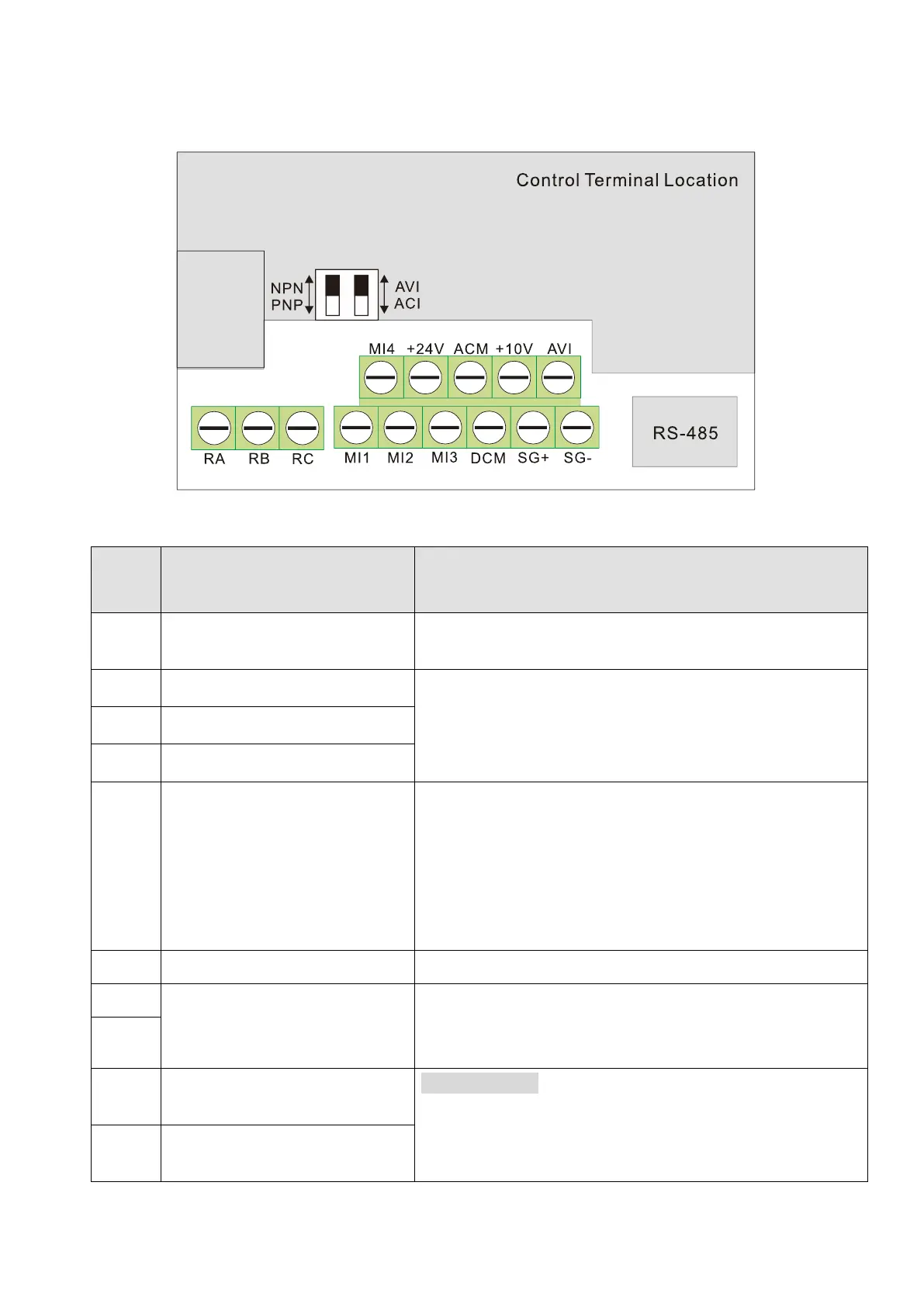
2-4 Control Terminals
2-4-1 Control Terminals Description
Terminal symbols and functions
Defaults (NPN mode) ON: Connect to DCM
ON: Run in MI1 direction
OFF: Stop acc. to Stop Method
Refer to Pr.04.06 to Pr.04.08 for programming the multi-
function inputs.
ON: the activation current is 5.5 mA.
OFF: leakage current tolerance is 10 μA.
Digital control signal common
(Source)
The +24V power total output capacity: 60 mA
1. When using MI terminal, the current capacity required
for the terminal operation should be deducted
accordingly (6 mA for each MI terminal).
2. Do NOT use it for excessive loads to avoid damage to
the internal circuit.
Digital Signal Common (Sink)
Common for multi-function input terminals.
Internally connected to RJ45 terminal PIN5 and PIN4,
providing flexible choice for users (only support one of
them at one time).
Multi-function Relay Output
(N.O.) a
Resistive Load:
5 A (N.O.) / 3 A (N.C.) 240 V
AC
5 A (N.O.) / 3 A (N.C.) 24 V
DC
Multi-function Relay Output
(N.C.) b
 Loading...