Chapter 2 Installation and WiringVFD-EL-W
26
Defaults (NPN mode) ON: Connect to DCM
Multi-function Relay Common
Inductive Load:
1.5 A (N.O.) / 0.5 A (N.C.) 240 V
AC
1.5 A (N.O.) / 0.5 A (N.C.) 24 V
DC
Refer to Pr.03.00 for programming
Potentiometer Power Supply
+10 V
DC
3 mA (Variable resistor 3–5 kΩ)
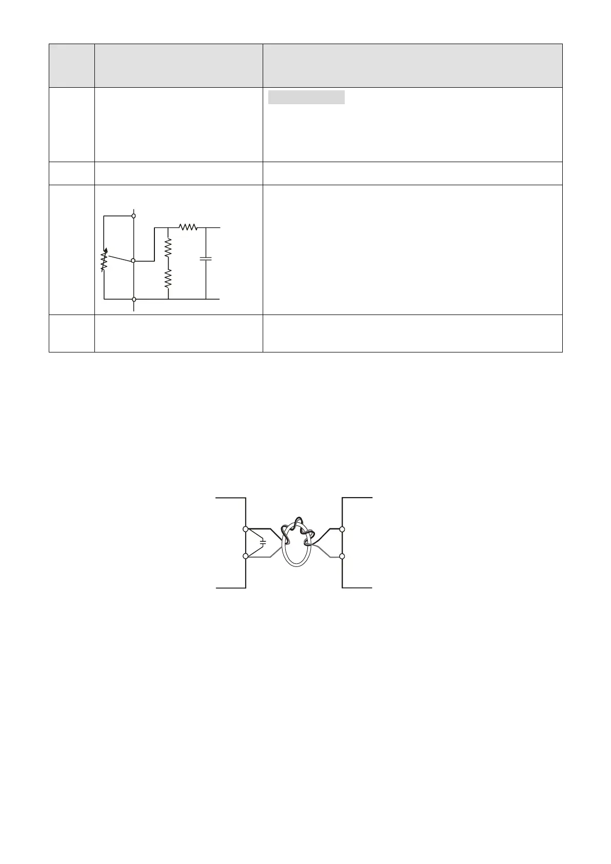
ACM
AVI
+10V
internal circuit
AVI circuit
Impedance: 47 kΩ
Resolution: 10 bits
Range: 0–10 V
DC
/4–20 mA =
0–maximum output frequency (Pr.01.00)
Selection: Pr.02.00, Pr.02.09, Pr.10.00
Setting: Pr.04.14–Pr.04.17
Analog Control Signal
(Common)
NOTE: Control signal wiring size: 18 AWG (0.75 mm
2
) with shielded wire.
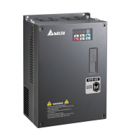
Analog inputs (AVI, ACM)
Analog input signals are easily affected by external noise. Use shielded wiring and keep it as short
as possible (< 20 m) with proper grounding. If the noise is inductive, connecting the shield to the
ACM terminal can cause improvement.
If the analog input signals are affected by noise from the AC motor drive, connect a capacitor (0.1
F and above) and a ferrite core as shown in the following diagrams:
Wind each wire three times or more around the core
Digital inputs (MI1, MI2, MI3, DCM)
When using contacts or switches to control the digital inputs, use high-quality components to avoid
contact bounce.