Chapter 4 Parameters|VFD-EL-W
146
Stopping
detection function
Pr.10.22 Set point deviation level
Pr.10.23 Set Point Stop Detection Time
Pr.01.12 Deceleration Time 2
Multi-pump system: all drives must
have the stopping detection function.
Set the related parameters for all
drives.
Pr.10.24 Deviation Level of Liquid
Leakage
Pr.10.25 Liquid Leakage Change
Detection
Pr.10.26 Liquid Leakage Deviation Level
Detection
All drives must have the restart
function for liquid leakage. Set the
related parameters for all drives.
Pr.10.14 Sleep Detection Time
Pr.10.15 Sleep Frequency
Pr.10.16 Wake-up Frequency
The multi-pump system has its own
wheel pump control function, the sleep
function is recommended to use only
for single pump drive function.
Multi-functional
pump function
Refer to the following description in
“Multi-communication application setting
case” for parameters setting according to
the functions of the Master and Slave
pumps.
Related parameters for PID set point and feedback value corresponds to the physical quantity
Determines the start-up display page after power is applied to the drive.
Gets into the self-check state first when the drive starts-up, after displays “Pon” and flashes for 5
sec., the drive turns to start-up page.
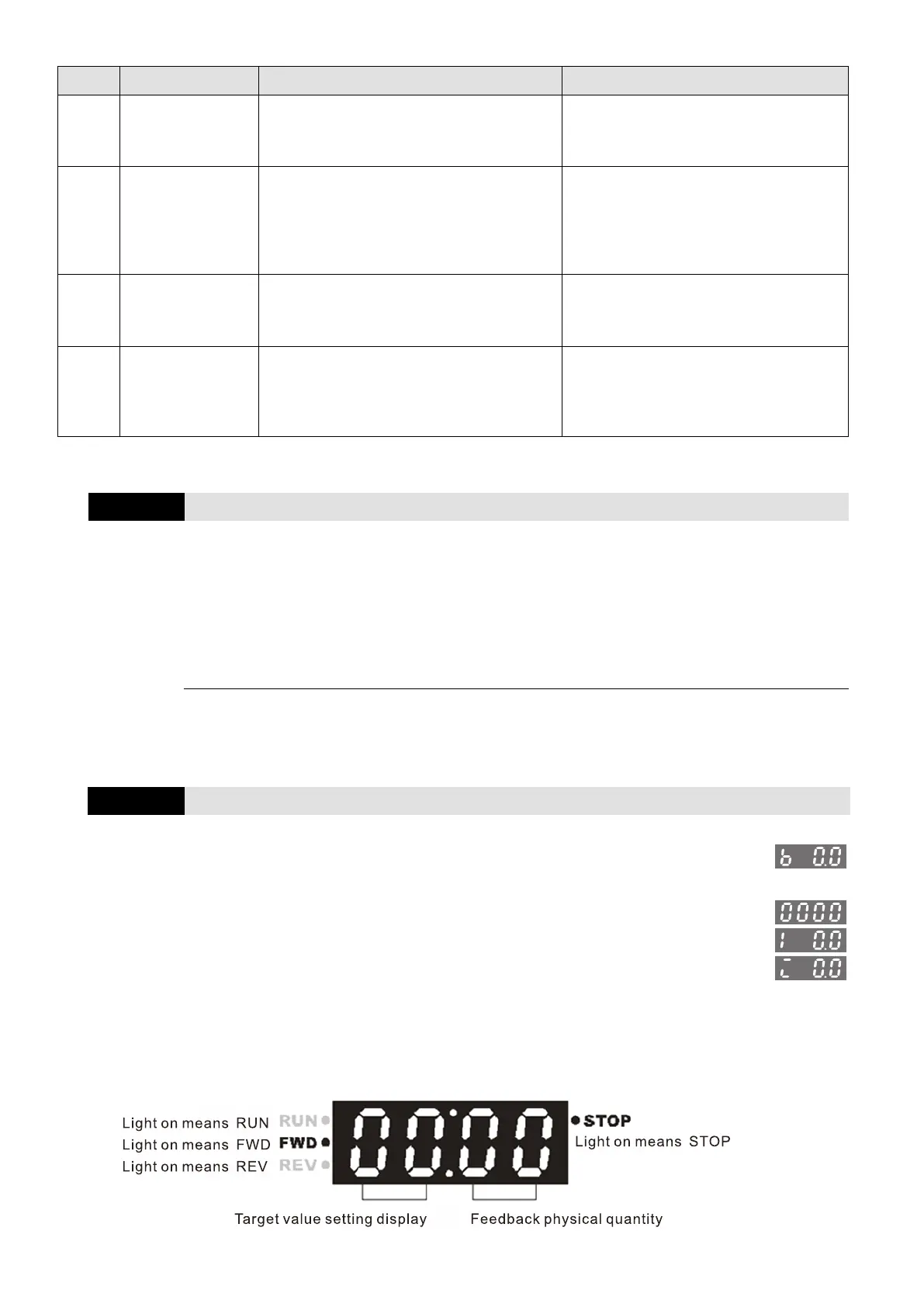
Content of Multi-function Display (User-Defined)
5: Display the PID feedback value after enabling the PID function
in %
8: Display the setting value and the feedback of PID control (P)
9: Display AVI analog input terminal signal (1.) (Unit: %)
10: Display AVI analog input terminal signal (1.) (Unit: %)
When Pr.00.03 is set to 3, use Pr.00.04 to select the displayed content as needed.
When Pr.00.04 = 5, the displayed PID feedback value is the percentage (%) of the terminal
measurement range.