5
VFD-B Series
DELTA ELECTRONICS, INC. ALL RIGHTS RESERVED
5-73
Group 11: Fan and Pump Control Parameters
11 - 00
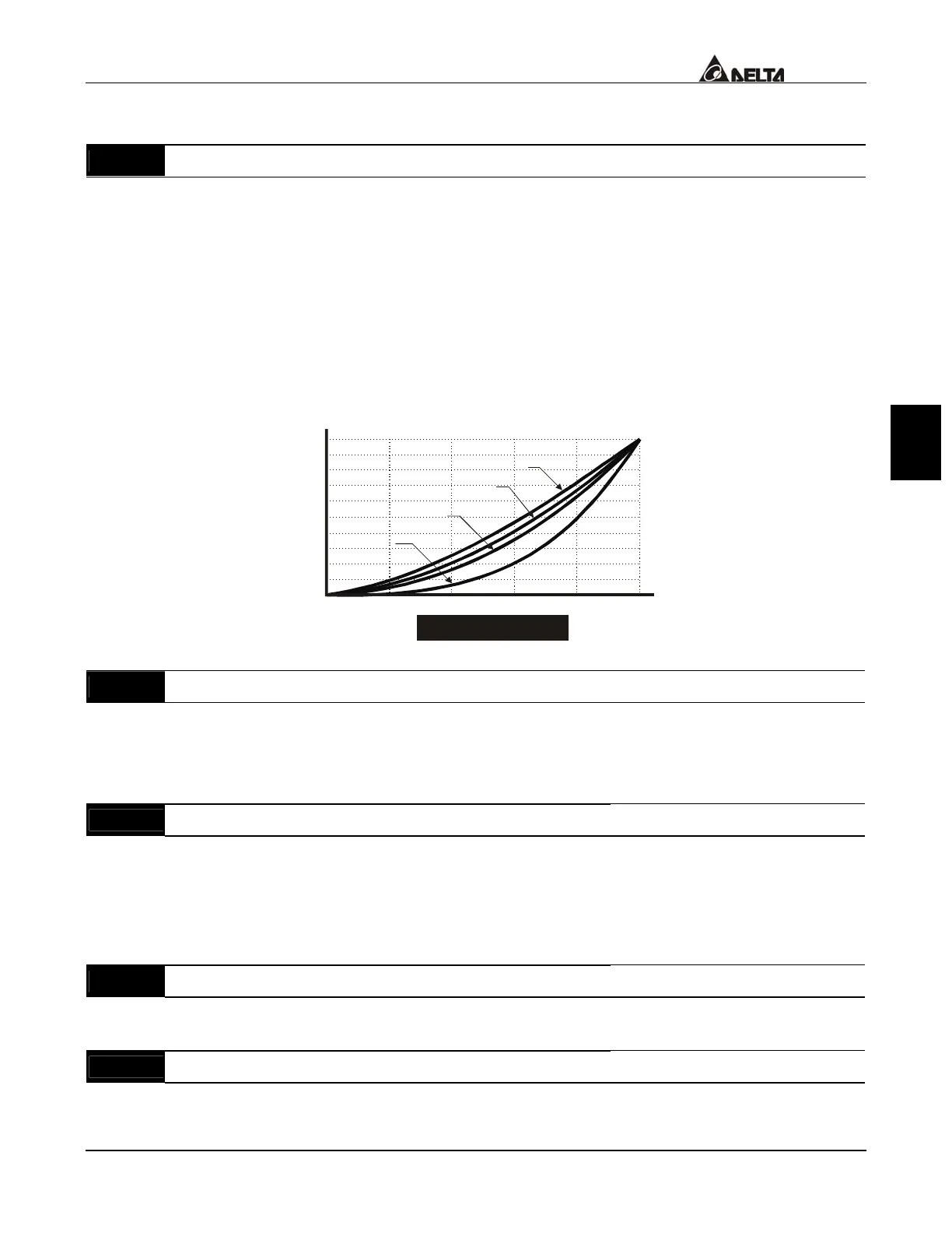
V / F Curve Selection
Factory Setting: 00
Settings 00 V/F curve determined by Pr.01-00 to Pr.01-06.
01 1.5 power curve
02 1.7 power curve
03 square curve
04 Cube curve
Confirm the curve of load and select the proper V/F curve before use.
V/F curve is shown as below:
02040
60
80
100
10
20
30
40
50
60
70
80
90
100
01-02
01-01
Voltage100%
Cube power curve
Square power curve
1.7 power curve
1.5 power curve
Freq. %
V/F Curve Diagram
11 - 01
Start-up Frequency of the Auxiliary Motor
Factory Setting: 0.00
Settings 0.00 to 120.00 Hz Unit: 0.01
This parameter serves as a reference for the startup value of the auxiliary motor; if the
setting is 0, the auxiliary motor cannot be activated.
11 - 02
Stop Frequency of the Auxiliary Motor
Factory Setting: 0.00
Settings 0.00 to 120.00 Hz Unit: 0.01
When Output Frequency reaches this parameter value, the auxiliary motor would come
to a stop. There is a minimum of a 5 Hz segment between the start frequency and stop
frequency of auxiliary motor. (Pr.11-01-Pr.11-02) > 5 Hz.
11 - 03
Time Delay before Starting the Auxiliary Motor
Factory Setting: 0.0
Settings 0.0 to 3600.0 sec Unit: 0.1
11 - 04
Time Delay before Stopping the Auxiliary Motor
Factory Setting: 0.0
Settings 0.0 to 3600.0 sec Unit: 0.1
 Loading...