Digital Ally, Inc. | Installation Instructions
3-3
DVM-800 Installation Guide | 860-00185-00 Rev L
Go Back To Table of Contents
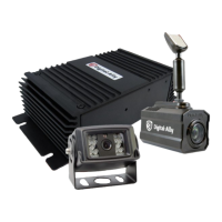
Step 3: Interface Box Installation
Interface Box
The IF Box must be securely mounted on a solid area of the
vehicle structure in a moisture free location where it can be
easily accessed for reset or replacement.
Possible mounting locations include:
• Under the dash on the passenger side.
• Behind the kick panel on the passenger side (or driver side).
• Mounted into the transmission tunnel sheet metal below the dash. On
some vehicles this is not advisable due to extreme heat radiated from
the transmission.
• Mounted on the exterior of the center console. Do NOT mount inside
the center console.
• Under the seat on some SUV-type vehicles.
• Behind a panel on the right hand side of the dash (nearest to the door).
• Do not place the IF Box directly on oorboard, or mount it in areas
where it could be exposed to moisture such as air conditioner
condensation, accidental liquid spills, rain, snow, mud, or other
elements that could be tracked into the vehicle.
• Do not place the IF Box in an area that will subject the unit to excessive
heat such as the transmission tunnel or engine rewall.
Mount the IF Box
1. Use the IF Box to DVM Cable as a gauge to estimate an appropriate location for
mounting the IF Box. Secure the IF Box to a location free from moisture.
2. Once a suitable mounting location has been identied for the IF Box, verify that
the shielding strap can be securely connected to the metal surface of the vehicle
chassis. If the shielding strap does not reach a suitable metal surface, reposition the
IF Box appropriately.
3. Secure the unconnected end of the shielding strap to the vehicle chassis.
4. The shielding strap must be connected to a metal surface of the vehicle chassis to
prevent electrical interference. Failure to properly connect the shielding strap may
cause system operation issues.
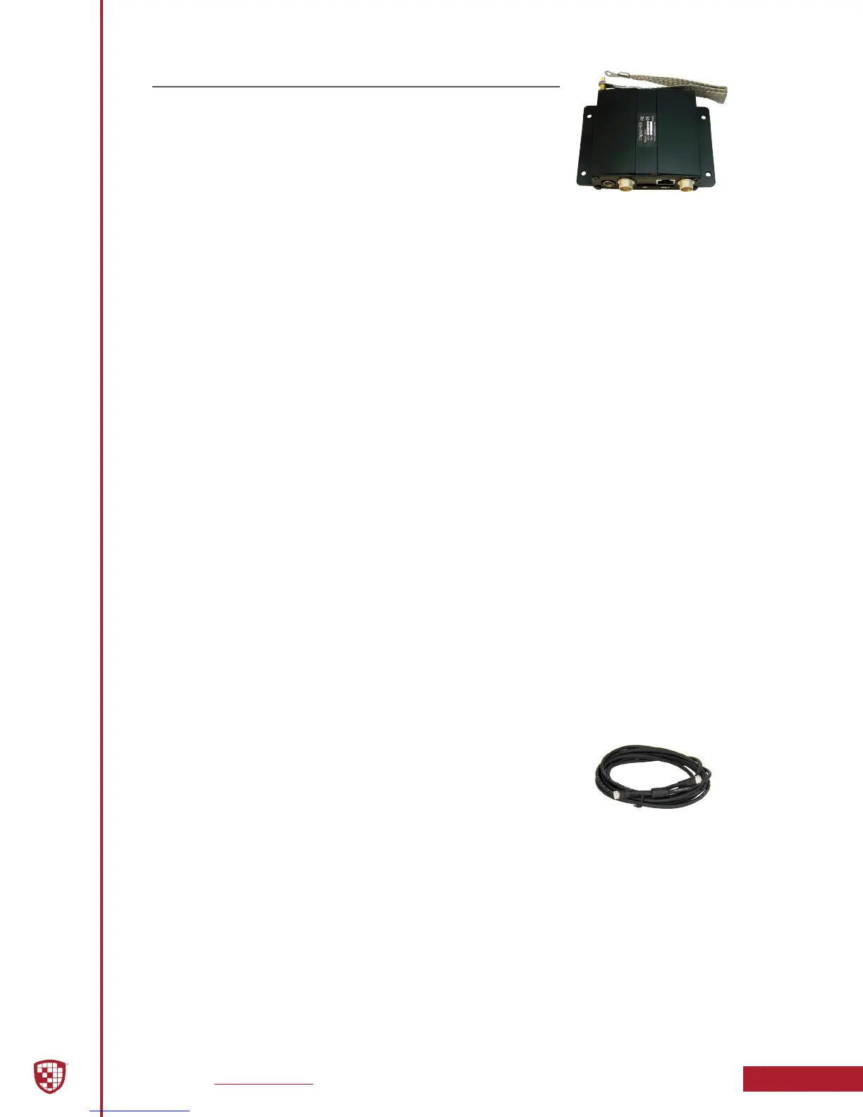
DVM to Interface Box Cable Installation
1. Plug the IF Box to DVM Cable into the back of the DVM.
2. Leaving slack in the cable at the mirror mounting bracket for
DVM adjustment, begin routing the cable from the DVM under the front edge of the
headliner down the windshield pillar towards the mounting location for the IF Box.
To conceal the cable, it may be necessary to loosen the sun visor mounting bracket
and/or other trim pieces to allow the cable to be tucked in behind the headliner.
3. Do not route wiring and cabling over any sharp metal edges. Avoid running the
cable parallel to other wiring and/or antenna coax from other equipment in the
vehicle. To prevent electrical shorts or breakage in the wiring and cabling, do not
allow wiring and cabling to be pinched behind trim pieces, panels, or other objects.
4. Secure the cable using velcro or standard tie wraps as required.
5. Plug the remaining end of the cable into the IF Box Mirror jack.
IF Box to DVM Cable
 Loading...