Digital Ally, Inc. | Installation Instructions
3-4
DVM-800 Installation Guide | 860-00185-00 Rev L
Go Back To Table of Contents
Step 4: Power, Ground, and Input Sensor
Power Cable Installation
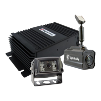
1. Plug the connector of the Main Power Cable into the IF Box.
2. Route the cable to a suitable location for electrical
connection.
3. Remove 4 to 5 inches of the outer jacket at the bare end of the power cable.
Separate the braided shield from the individual conductors, attach an electrical
terminal to the end of the braided shield, and attach the terminal to the chassis of
the vehicle.
4. Connect the Red wire of the power cable to the vehicle Positive battery terminal
and the Black wire of this power cable directly to the vehicle’s chassis. It is required
that the power wires be connected to the battery with no obstructions such as a
cuto switch or charge guard system.
5. Connect the White wire to the ignition switch where +13.8VDC is only present when
the vehicle ignition key is in the ON position.
Figure 3-4: Power Connections
Input Color
Power
Connect to +13.8VDC Battery Terminal
Red
Ignition
Connect to +13.8VDC Ignition Switch
White
Ground
Vehicle Chassis
Black
6. Secure the cable and the inline fuse housing using Velcro or standard cable ties
as required. The cable contains a 5 Amp, 250V fuse and a lter to help minimize
unwanted RF noise.
7. Re-connect the cable to the connector on the back of the DVM.
Main Power Cable

 Loading...