 Loading...
Do you have a question about the Dimplex Quantum series and is the answer not in the manual?
| Operation | Quiet operation |
|---|---|
| Adjustable Thermostat | Yes |
| Timer | Yes |
| Weight | Varies by model |
| Dimensions | Varies by model |
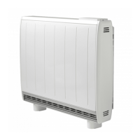
| Color Options | White |
| Energy Efficiency | High |
| Programming | 24/7 Programmable |
| Safety Features | Overheat protection |
| Voltage | 230-240V |
| Remote Control | Via smartphone app (depending on model) |
Provides essential safety advice and highlights key operational warnings.
Key warnings for operation and mandatory requirements for electrical installation.
Ensures secure electrical connections to prevent ignition risks.
Guidelines and warnings to ensure the safety of children around the appliance.
Critical warnings regarding earthing, hazardous voltage, and live parts.
Precautions for secure fixing, fire hazards, and safe handling of the heavy appliance.
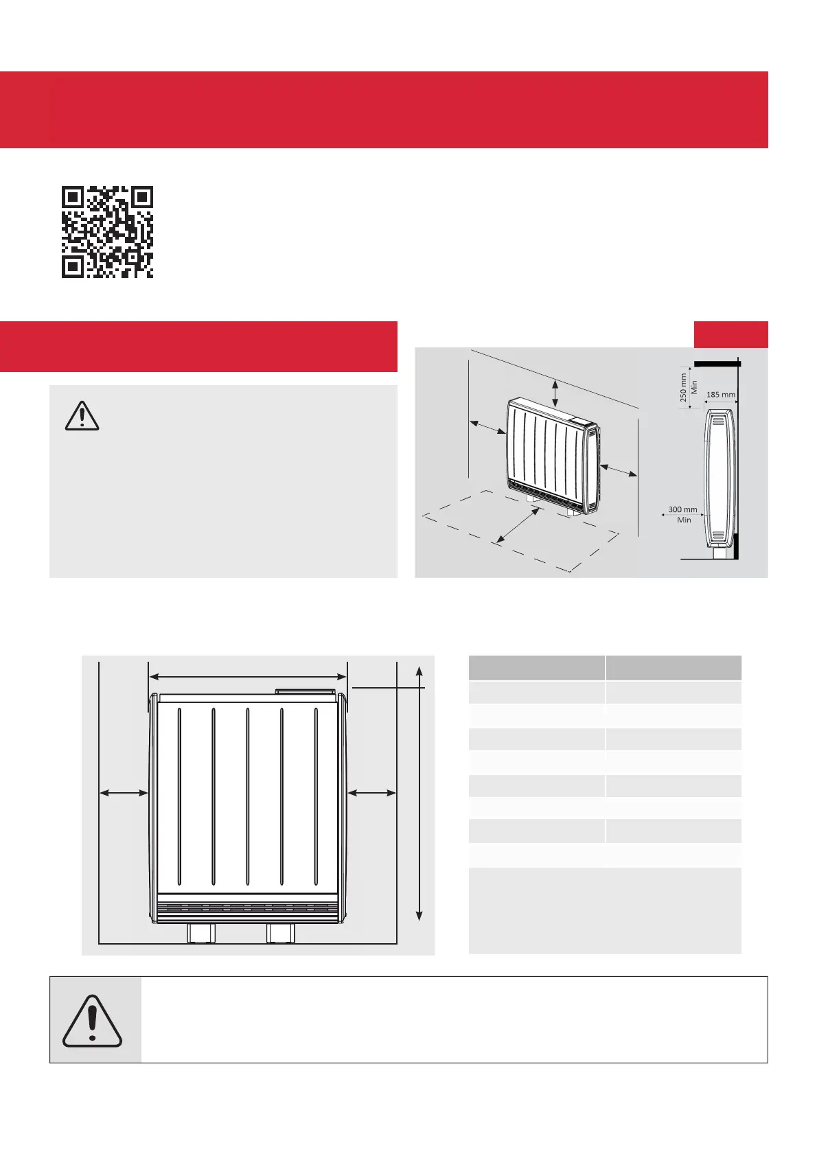
Required clearances around the heater for safe operation.
Description of the heater's control panel, buttons, and display.
Detailed steps for navigating menus, using the dial, and understanding interface functions.
Details on Open Window Detection and Adaptive Start features for efficiency.
Explanation of timer modes for efficient heating based on demand.
Instructions for activating Boost mode for temporary heating.
Methods to lock the heater's controller to restrict access to functions.
List of fault codes and their corresponding descriptions for troubleshooting.
Mandatory requirements for securely fixing the heater to the wall.
Final steps for securing the heater to the wall and handling cells.
Wiring configuration for dual supply (peak and off-peak) installations.
Specific requirements for single peak supply installations.
Instructions for handling and positioning energy cells around elements.
Procedure for enabling and setting the heater's PIN lock.
Checklist for casing, power, and single supply charge time setup.