25OPERATION AND INSTALLATION INSTRUCTIONS MN280075EN July 2018
Form 6 microprocessor-based rack-mount recloser control
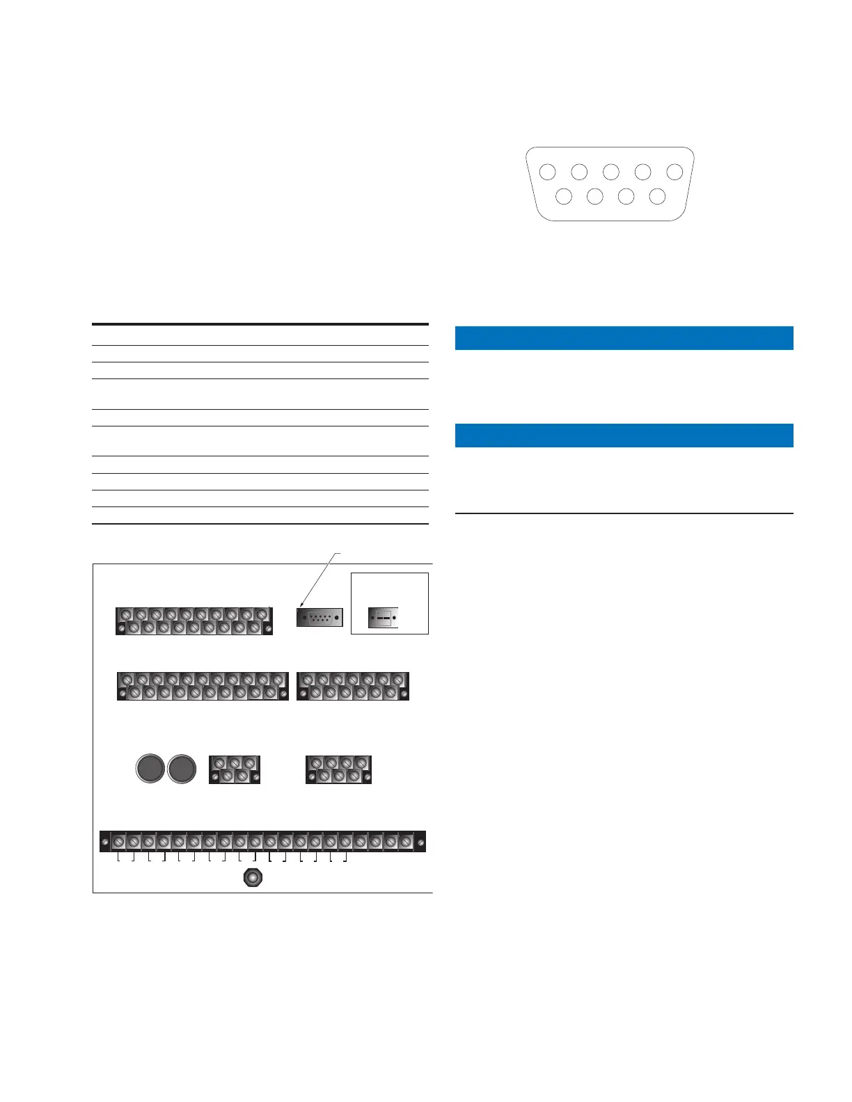
Rear panel RS-232 communication port
pin assignments
Table9 indicates the pin assignments for the rear
panel RS-232 communication port (Figure17). Refer to
Figure18 for pin identification. Refer to Protocols for
additionalinformation.
Refer to the Accessories section of this manual for
additional communication options.
Table9. Rear panel RS-232 communication port pin
assignments
Pin Number Signal Name
1 DCD Carrier Detect
2 RXD Receive Data
3 TXD Transmit Data
4 DTR
Data Terminal Ready
(Not Connected)
5 GND Signal Ground
6 DSR
Data Set Ready
(Not Connected)
7 RTS Request to Send
8 CTS Clear to Send
9 NC Not Used
10 (Shroud) Chassis Ground
TB1
1
2
35 7911 13 15 17 19
46 81012141618
CI1
CI2 CI3 SS1 CO1
CO2 CO3
CO4
CI4
CI1 CI2 CI3 SS1 CO1 CO2 CO3 CO4
TB3
1
3
579111315171921
CI5 CI6 CI7 CI8 CI9 CI10 CI11 CO5 CO6
TB4
2
46 81012141618
20
CI4 CI5 CI6 CI7 CI8 CI9 CI10 CI11 CO5
CO6
13
5
7911 13
CO7 CO8
CO9 CO10 CO11
CO12
2
46 81012
CO7 CO8 CO9 CO10 CO11CO12
FUSE
(10 AMP)
FUSE
(10 AMP)
TB5
+
1
-
5
2
-
4
+
INPUT POWER AUXILIARY POWER
28 VDC
RECLOSER INTERFACE CONNECTIONS
A
1
D
3
F
57
2
B
4
C
6
E
TB6
TB2
•
12
•
34
•
56
•
78
•
910
•
11 12
•
13 14
•
15 16
•
17 18
•
19
20
I
(1-2)
I
(3-4)
I
(5-6)
V
(1-2)
V
(3-4)
V
(5-6)
V1
I
(SEF)
J1-RS-232
IRIG-B
RS-232 DTE
RS-232 Serial
Communication Port
Figure17. Form 6 recloser control rear panel RS-232
communication port
RS-232 DTE
J1-RS-232
12
3
45
6
7
89
Figure18. Rear panel rs-232 communication port
pinidentification
Using removable inserts
NOTICE
Control damage. De-energize both AC and DC power
prior to removing or installing any internal connections
or circuit boards in the control. Failure to comply can
result in damage to the control. T241.1
NOTICE
Equipment damage. Always wear a grounding wrist
strap to control static electricity before handling circuit
boards. Failure to use this strap may result in circuit
board damage. T253.1
The front panel inserts can be changed, if desired.
1. De-energize both AC and DC power.
2. Use a flathead or 3/33" hex key screwdriver to unscrew
the six front panel screws.
3. Pull the right side of the front panel out towards the left
(Figure19).
ote:N Various connecting wires will keep the panel attached
to the control.
ote:N It is not necessary to disconnect any wires.
 Loading...


