44 OPERATION AND INSTALLATION INSTRUCTIONS MN280075EN July 2018
Form 6 microprocessor-based rack-mount recloser control
Figure40. Using a manual closing tool to operate
the recloser
Return the control to service
WARNING
This equipment is not intended to protect human
life. Follow all locally approved procedures and safety
practices when installing or operating this equipment.
Failure to comply can result in death, severe personal
injury, and equipment damage. G102.1
After the required work or testing is completed, follow this
procedure to return the control to service:
CAUTION
Equipment misoperation. Do not connect this control
to an energized recloser until all control settings have
been properly programmed and verified. Refer to the
programming information for this control. Failure to
comply can result in control and recloser misoperation,
equipment damage, and personal injury. G110.3
1. Verify that all control settings are correct prior to
installation.
WARNING
Hazardous voltage. Recloser and control must
be solidly grounded. Follow all locally approved
procedures and safety practices when grounding this
equipment. Improper grounding can result in contact
with high voltage, which will cause death or severe
personalinjury. G115.1
2. Connect the ground to the control.
ote:N Refer to Grounding the control section.
TB1
1
2
35 7911 13 15 17 19
46 81012141618
CI1
CI2 CI3 SS1 CO1
CO2 CO3
CO4
CI4
CI1 CI2 CI3 SS1 CO1 CO2 CO3 CO4
TB3
1
3
579111315171921
CI5 CI6 CI7 CI8 CI9 CI10 CI11 CO5 CO6
TB4
2
46 81012141618
20
CI4 CI5 CI6 CI7 CI8 CI9 CI10 CI11 CO5
CO6
13
5
7911 13
CO7 CO8
CO9 CO10 CO11
CO12
2
46 81012
CO7 CO8 CO9 CO10 CO11CO12
FUSE
(10 AMP)
FUSE
(10 AMP)
TB5
+
1
-
5
2
-
4
+
INPUT POWER AUXILIARY POWER
28 VDC
RECLOSER INTERFACE CONNECTIONS
A
1
D
3
F
57
2
B
4
C
6
E
TB6
TB2
•
12
•
34
•
56
•
78
•
910
•
11 12
•
13 14
•
15 16
•
17 18
•
19
20
I(1-2)
I(3-4) I(5-6) V(1-2)
V(3-4) V(5-6) V1
I(SEF)
J1-RS-232
IRIG-B
RS-485
RS-232 DTE
C + –
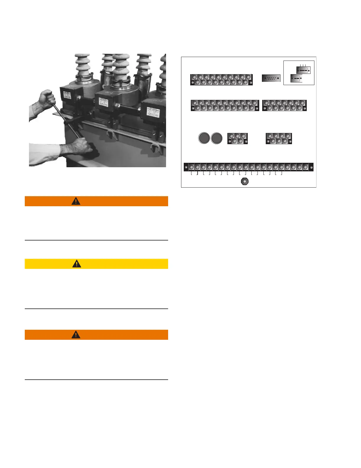
Figure41. Back of Form 6 rack mount recloser control
3. Use a screwdriver to re-connect all wiring on terminal
block TB2 (Voltage/Current Inputs) to the control
(Figure41).
4. Connect any serial communications ports and IRIG-B
timing connection (Figure41).
5. Connect terminal block TB5 to the control by screwing
the mounting screw through each side of the terminal
block (Input Power) and into the control (Figure41).
6. Connect any control input and status output wiring to
TB1, TB3, and TB4 (Figure41).
7. Connect terminal block TB6 to the control by screwing
the mounting screw through each side of the terminal
block (Recloser Interface Connections) and into the
control (Figure41).
8. Connect control AC sensing voltage to the control via
disconnect switches.
ote:N Refer to Customer connections for DC power and
AC voltage sensing section.
9. Connect DC power to the control via
disconnectswitches.
ote:N Refer to Customer connections for DC power and
AC voltage sensing section.
 Loading...


