32 OPERATION AND INSTALLATION INSTRUCTIONS MN280075EN July 2018
Form 6 microprocessor-based rack-mount recloser control
Discrete interface board (DIF) option accessory
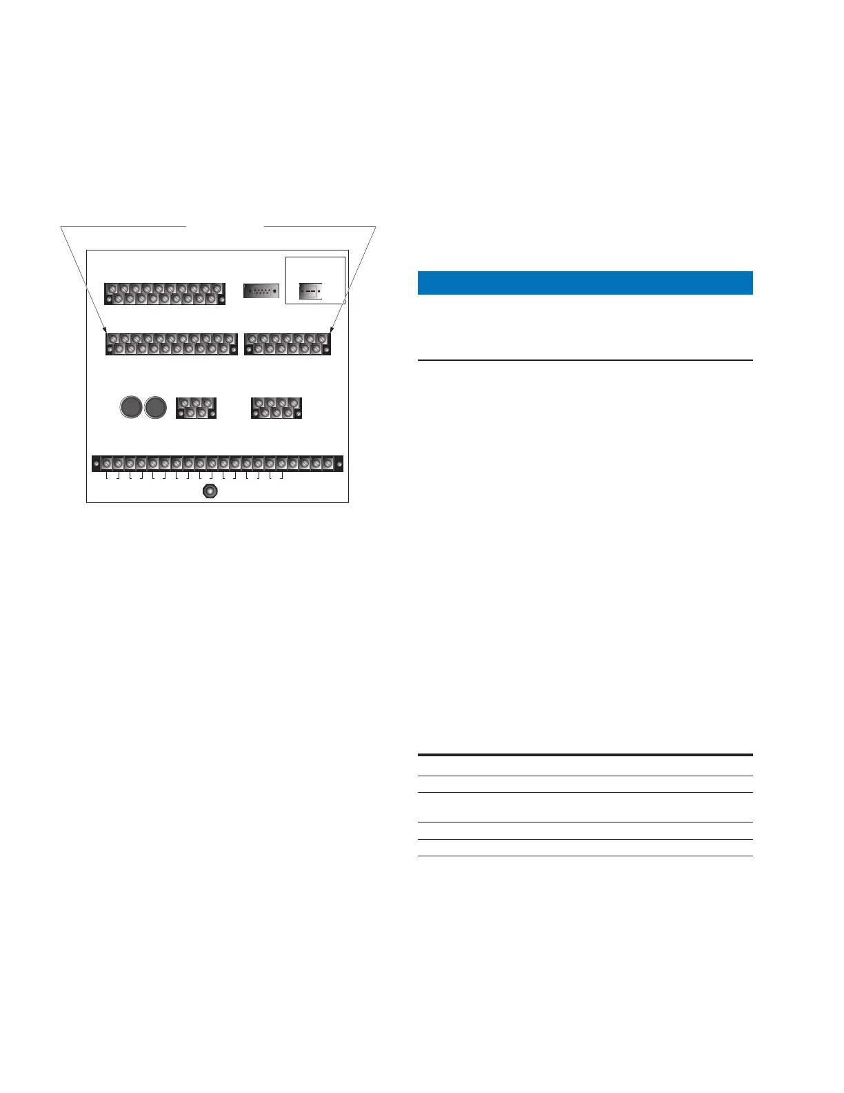
A Discrete Interface Board Option accessory provides eight
configurable input control contacts and eight configurable
output status contacts (Figure27). The ordering options
include: Standard (3 inputs / 5 outputs) or Additional
(8inputs / 8 outputs).
TB1
1
2
3 57911 13 15 17 19
46 81012141618
CI1
CI2 CI3 SS1 CO1
CO2 CO3
CO4
CI4
CI1 CI2 CI3 SS1 CO1 CO2 CO3 CO4
TB3
1
3
579111315171921
CI5 CI6 CI7 CI8 CI9 CI10 CI11 CO5 CO6
TB4
2
46 81012141618
20
CI4 CI5 CI6 CI7 CI8 CI9 CI10 CI11 CO5
CO6
13
5
7911 13
CO7 CO8
CO9 CO10 CO11
CO12
2
46 81012
CO7 CO8 CO9 CO10 CO11CO12
FUSE
(10 AMP)
FUSE
(10 AMP)
TB5
+
1
-
5
2
-
4
+
INPUT POWER AUXILIARY POWER
28 VDC
RECLOSER INTERFACE CONNECTIONS
A
1
D
3
F
57
2
B
4
C
6
E
TB6
TB2
•
12
•
34
•
56
•
78
•
910
•
11 12
•
13 14
•
15 16
•
17 18
•
19
20
I(1-2)
I(3-4) I(5-6) V(1-2)
V(3-4) V(5-6) V1
I(SEF)
J1-RS-232
IRIG-B
RS-232 DTE
DIF Board Accessory
Figure27. Form 6 recloser control discrete interface
board accessory
Mounting kits
The Form 6 rack mount recloser control is designed to be
mounted in a standard 19" rack. There are three mounting
kits available:
Single Rack Mount – KME6-1802 Mounting Kit includes
two handles. Refer to Single rack mount option handle
attachment instructions.
Double Rack Mount – KME6-1803 Mounting Kit includes
two handles and one connecting plate. Refer to Double
rack mount connecting plate and handle attachment
instructions.
Single Mount w/Filler Plate – KME6-1804 Mounting
Kit includes two handles and one filler plate. Refer to
Double Rack – Single Mount Handle and Filler Plate
Attachment Instructions.
Refer to Service Information MN280078EN Form 6 Rack
Mounting Kit Instructions for additional information.
Double rack mount connecting plate and handle
attachment instructions
These instructions apply to the attachment of the handles
and connecting plate to the Form 6 Double Rack Mount
Recloser Control.
These controls are shipped without the handles or
connecting plate attached. Refer to Figure28 and Figure29
and follow this procedure to attach the handles and
connecting plate and then secure the two controls together.
NOTICE
Control damage. De-energize both AC and DC power
prior to removing or installing any internal connections
or circuit boards in the control. Failure to comply can
result in damage to the control. T241.1
Attach control handles
1. Orient the handles and controls as illustrated in the
Front View in Figure28.
2. Attach one handle (Item 2) to each control (Item 1)
using three #10-32 Flat Head Screws (Item 3) per
handle as illustrated in Figure28.
3. Completely tighten hardware. Do not torque.
Attach connecting plate
1. Remove the two middle screws from the back of each
control with a Phillips head screwdriver as illustrated in
Figure28.
2. Place the connecting plate over the screw holes in
thecontrols.
3. Secure the connecting plate with the previously
removed screws.
4. Completely tighten hardware. Do not torque.
Table12. Form 6 recloser control double rack mount
accessory attachment parts list (Figure28)
Item Description Part Number Quantity
1 Form 6 Control 2
2 Form 6 Handle 6A00163901 2
3
#10-32 Fl Hd
Screw
722915310050A 6
4 Connecting Plate 6A00169501 1
5 #10-24 Screw 813315110100A 2
 Loading...


