bushings. For example, to regulate the voltage between
phase A and phase C, the phase A regulator would have
to have knowledge of the voltage between the SA and SC
bushings. Before the MP control was available, the only
method of obtaining this voltage would be to use a potential
transformer positioned between the source bushings on the
two adjacent voltage regulators.
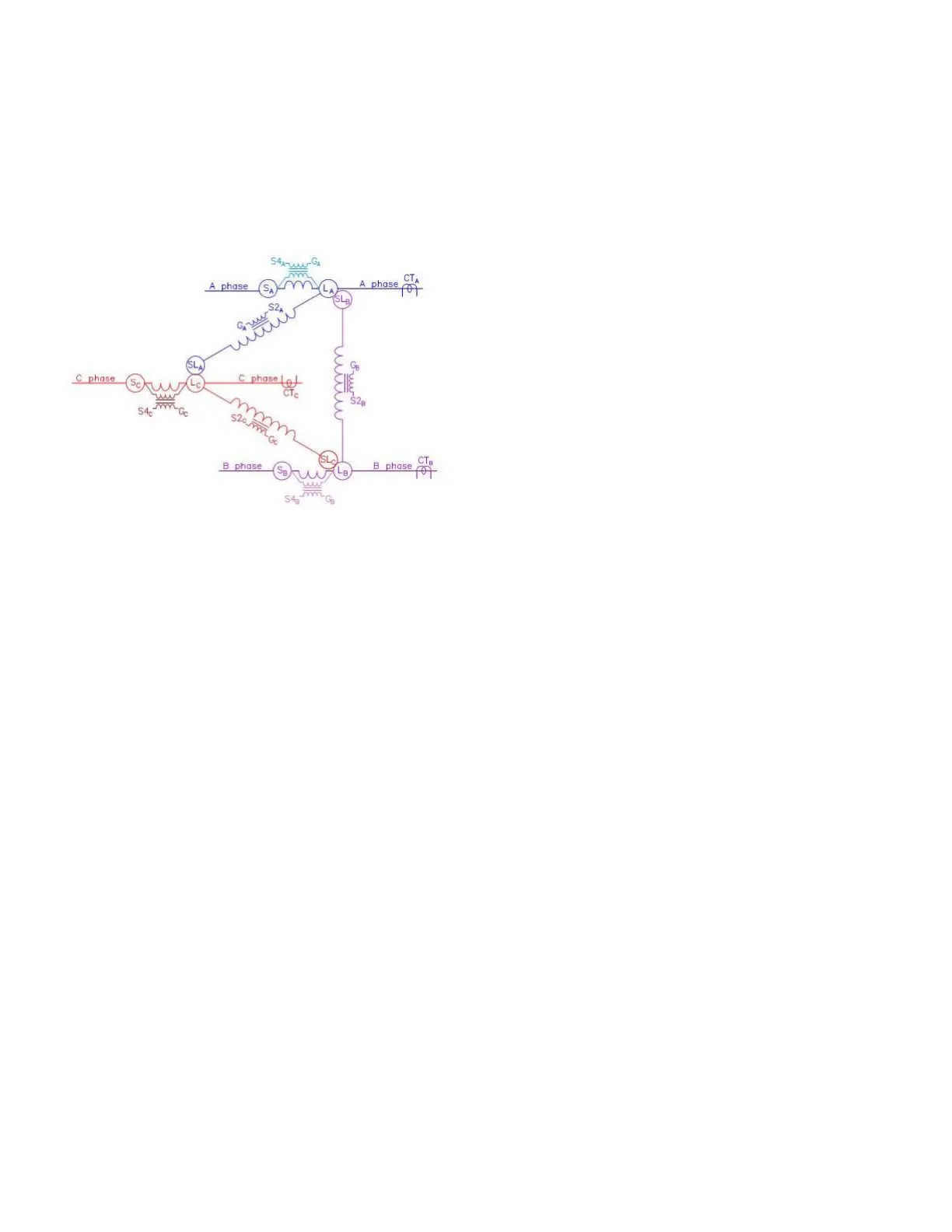
Figure44. Three type B regulators connected in a
closed-delta
Because the MP control is connected to all three regulators
in the close delta arrangement, all data is known and
available to the one control. Using the DeltaCalc feature, the
control can now do accurate regulation for delta connected
voltage regulators when power flow is in reverse.
DeltaCalc settings for closed delta
When using DeltaCalc with closed delta configured
regulators, the three settings options available are Off,
Basic, and Advanced. The Off setting will result in
traditional closed delta voltage regulation for the three
phases.
The Basic setting option enables the DeltaCalc feature
to determine and use voltage information from adjacent
voltage regulators to effectively perform voltage regulation
in the reverse direction. For regulation in the forward
direction, there is no difference between Off and the Basic
DeltaCalc settings.
In addition to the functions performed in the Basic
DeltaCalc operation, the Advanced setting enables the
control to determine the best method of affecting regulation
between the three phases for forward and reverse power
operations. The control will analyze the out-of-band
conditions between all phases and determine how to best
operate the regulators to bring the voltages between all
three phases back into band with the fewest number of tap-
changer operations. Without the DeltaCalc feature, in-band
stability will usually take a few extra operations as the
control of a particular phase may be forced to respond to an
out-of-band condition created by the operation of a regulator
on an adjacent phase. The DeltaCalc feature will eliminate
some of the back-and-forth tapping operations required to
find stable in-band voltages between all three phases.
Voltage limiter
The voltage limiter feature is used to place both a high
and low limit on the output voltage of the regulator. When
enabled, it operates in either the forward or reverse
directions and has one of the highest priorities of all
operating functions. Voltage limiter is overridden only when
Auto Operation Blocking Status (FC 69) is set to Blocked,
when an operator takes local control or through an inter-
connected SCADA system. When the voltage limiter IVVC
(integrated volt/var control) settings are used, voltage limiter
also takes priority over remote SCADA tapping operations.
The purpose of the voltage limiter is to protect the
consumer from abnormally high or low voltages resulting
from:
Large, rapid changes in transmission voltage
Abnormal loading of the feeder
Inaccurate regulator control settings (voltage level,
bandwidth, and line-drop compensation)
Heavy loading by the first customer while there is a
leading power factor on the feeder
Light loading at the first customer with heavy loading on
the feeder at the same time
The appropriate high and low limits for the output voltage
can be programmed into the control at FC 81 and FC 82,
respectively. The feature is then activated by accessing
FC 80 and entering the desired operation: Off; High Limit
Only; High/Low Limits; IVVC High Limit Only; or IVVC High/
Low Limits. If low-voltage limiting only is desired, FC 80
should be set for both high and low limiting and an extreme
value programmed into FC 81 for the high limit (e.g.135) to
prevent the high limit from activating.
As mentioned earlier, when one of the IVVC voltage limiter
settings are selected at FC 80, the voltage limiter settings
in the control take priority over SCADA controlled motor
operations. IVVC software typically has the ability to enforce
voltage limits, but this is not always the case. When IVVC
software is not able to impose voltage limiter limits, these
setting will impose the limits through the control.
The control has two response sensitivities and the response
time for each sensitivity is configurable. If the output
voltage exceeds either the high or low limit by 3 V or
more, the control samples the voltage for the period time
specified at FC 83 and then taps immediately to bring the
voltage to the limit value. If the output voltage exceeds
either the high or low limit by less than 3 V, the control
samples the voltage for the period specified at FC 84 and
then taps to bring the voltage to the limit value. The control
uses the sequential method of tapping, with a time delay
between the completion of one tapping operation and
the beginning of the next set at FC 85, when bringing the
voltage back to the limit value. Voltage Limiter High and
Voltage Limiter Low LEDs on the front panel illuminate to
indicate when either limit is active.
To avoid potential cycling of the regulator, set the high-and
low-voltage limits at lest two volts above and below the
upper and lower bandwidth limits. This will establish a "grey
zone" between the high-and low-voltage limits and the
138
INSTALLATION, OPERATION, AND MAINTENANCE INSTRUCTIONS MN225003EN April 2018
CL-7 Voltage Regulator Control
 Loading...


