The Fault Detect feature can also be used in conjunction
with Status Alarms. When levels of fault detection are
included in the list of active alarms and one of the fault
detection criteria are met, this condition will activate
the alarm. The active alarm status can then be used to
trigger profiler data recordings, illuminate an LED, or drive
configurable logic.
Heater
The CL-7 control is equipped with a cabinet heater as a
standard feature. The heater is incorporated into the control
hardware and no action is required to enable or control the
operation of the heater.
Battery options
The CL-7 control may be equipped with a 13 A-Hr, 24 Vdc
battery backup. The purpose of the battery backup is to
maintain power to the control when system power is lost.
The battery is not intended to run the tap-changer.
When the control is equipped with battery backup, the
function codes are used to monitor battery function. When
the battery is in use, FC 190 will display battery current
and voltage values. Use FC 191 to initiate a battery test
and display the results. An automatic battery test can be
enabled at FC 192 which will run a battery test within 60
seconds of power up of the control and then every 12 hours
thereafter.
Battery test results may display a code when the test is not
successfully passed. The codes are:
1 – Battery failed test
2 – A battery test was already running
3 – Battery test was blocked
4 – Battery test was not run
5 – Auto battery test disabled.
Figure 58. Auxiliary control box with backup batteries
Customer supplied battery power
The CL-7 control can be powered using a substation battery
with a voltage of 48 to 125 Vdc. With this option, terminals
will be provided on the back panel of the control to connect
battery power. The terminals will be connected to the
control DC power jumper (see Figure 54). If a substation
batter option is not provided, the DC power jumper must be
in place in order to power the control.
Figure 59. DC power jumper in place on side of control.
This jumper must be in place to power the control when
the substation battery option is not provided
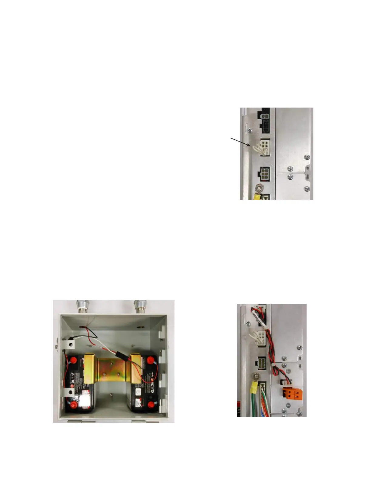
DC power supply (13.5 Vdc)
An optional 13.5 Vdc power supply is available for the CL-7
control. The power supply is intended to provide an auxiliary
source to power communications equipment. The unit has a
max output of 1.48 A for 1 second and max power of 14 W
continuous and 20 W peak.
Figure 58 shows the DC power supply installed in the side
of a CL-7 control. Power connections can be made to the
orange plug; the top plug is the negative terminal and the
bottom plug is the positive terminal.
Figure 60. DC power supply (13.5 Vdc) installed in the
side of a CL-7 control
157
INSTALLATION, OPERATION, AND MAINTENANCE INSTRUCTIONS MN225003EN April 2018
CL-7 Voltage Regulator Control
 Loading...


