Programming and reconfiguring for different voltage
systems
Reconfiguring a voltage regulator for a new system voltage
requires more than just programming the control. System
voltage changes will require control programming, ratio
correction transformer (RCT) connection changes and
in some cases, a change in the control winding (PT) tap
connection inside the regulator tank through the hand-hole
cover.
Refer to the regulator nameplate voltage chart for
information on programming and reconfiguring the regulator.
The Internal PT Ratio, RCT connection and Overall PT Ratio
can be found for common system Load Voltages. If the
desired system voltage is not show on the nameplate, refer
to Allowable system voltages and calculation of overall
PT ratio in this section of this manual. Instructions for
setting Regulator Configuration (FC 41) can be found in the
Determination of leading or lagging in delta-connected
regulators in this section of this manual.
WARNING
Explosion Hazard. Bypass a regulator with the line
energized only if the position indicator, the neutral
light, and the control tap position indicate neutral and
the voltage measured between the source and load
bushings using an approved voltmeter is zero. If both
neutral indicators do not indicate neutral or there is a
voltage between the source and load bushings, the line
should be de-energized to avoid shorting part of the
series winding and resultant high circulating current.
Failure to comply can result in death or personal injury
and equipment damage. VR-T206.1
Steps for changing system voltage
1. Remove the nameplates from the unit and move the
pins to the desired Load Volts.
2. Refer to the nameplate; if the Control Winding Taps
must be changed the voltage regulator must be
de-energize. Refer to the section Removal from
Service in document MN225008EN VR-32 Voltage
Regulator with Quik-Drive Tap-Changer Installation,
Operation and Maintenance Instructions for detailed
instructions.
3. Open the hand-hole cover and reconfigure the control
winding connections on the terminal board on top of
the tap changer.
a. Move the PT tap connection (E tap) to the correct
position. The terminal is bladed and should easily pull
off and then slide onto the new connection point (E1,
E2 or E3).
b. If the regulator is equipped with an internal differential
PT (IDPT) there will be a reference to a P tap on the
nameplate for the control winding tap. Reconnect the
P tap as required (P1, P2 or P3).
4. Replace and secure the hand-hole cover.
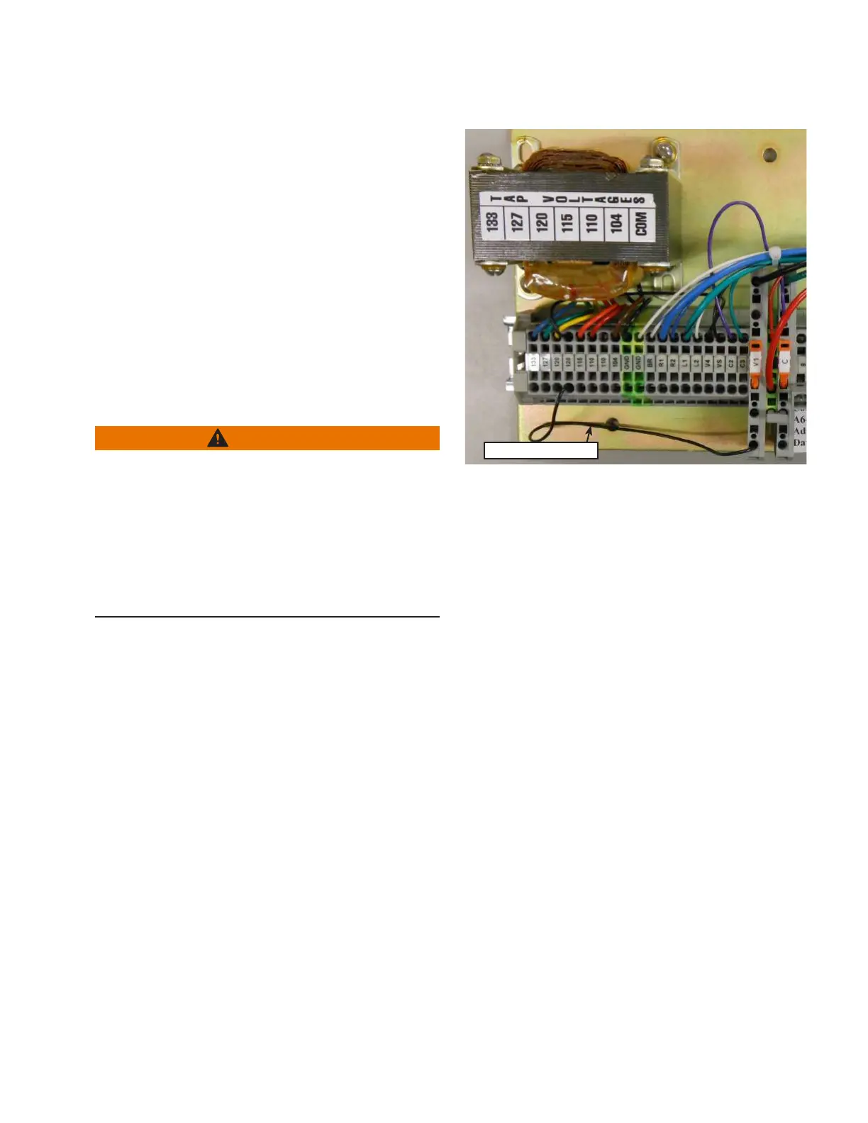
RCT Adjustment Wire
Figure14. Ratio correction transformer showing wire for
voltage adjustment
5. The control should be powered down for the next step.
To do so:
a. Move the CONTROL FUNCTION switch to OFF
b. Move the POWER switch to OFF.
c. On the back panel, Open the V1 and V6 (if present)
switches and close the C switch (see Figure14).
6. Connect the RCT as required for the desired system
voltage.
a. Standard Short Back Panel – Move the single black
wire connected below TB3 to the correct RCT
connection point (see Figure14)
b. Full Back Panel – Move the looped tagged black wire
connected on the left side of the RCT terminal board.
c. IDPT RCT – If there is a second RCT for the IDPT,
move the looped tagged white/brown wire connected
on the left side of the RCT2 terminal board.
7. Power the control for programming:
a. Internal Power – If the regulator is connected to
system power, close the V1 and V6 (if present)
switches and open the C switch and move the
POWER switch to INTERNAL.
b. External Power – Refer to Section1: Control Front
Panel: Connecting power to external source
terminals for detailed instructions on applying
power to the external source terminals. Once power
has been connected, move the POWER switch to
INTERNAL.
21
INSTALLATION, OPERATION, AND MAINTENANCE INSTRUCTIONS MN225003EN April 2018
CL-7 Voltage Regulator Control
 Loading...


