Wiring diagrams and schematics
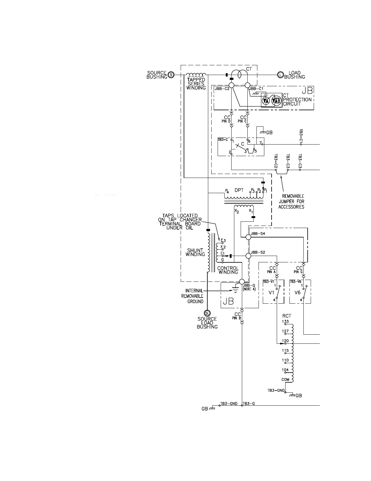
Figure 62. Wiring diagram for Type B VR-32 regulator and CL-7 control with differential potential transformer
Notes:
1. Portions of schematic shown in dotted enclosure is located in
regulator tank.
2. Motor resistor required for QD3 tap-changer only. Connection is
direct for QD5 and QD8 tap-changers.
3. This switch is normally closed for QD3 and normally opened for
QD5 and QD8 tap-changers.
4. The two JBB-G points shown are physically one connection point in
the junction box.
C CT Shorting Switch
CC Control Cable
CT Current Transformer (Toroidal Coil)
DPT Differential Potential Transformer
DHR Drag Hand Reset
EST External Source Terminals
GIB Ground Integrated into Terminal Board
HSL Holding Switch Lower
HSR Holding Switch Raise
IRS Indicator Reset Solenoid (Position
Indicator)
JB Junction Box on the Regulator Cover
JBB Junction Box Terminal Board
on the Cover
LLS Lower Limit Switch (Position Indicator)
LLS Lower Logic Switch (Tap-Changer)
LSS Lower Safety Switch
MC Motor Capacitor
MF Motor Fuse
MR Motor Resistor
NL Neutral Light
NLS Neutral Light Switch
PS Power Switch
RCT Ratio Correction Transformer
RLS Raise Limit Switch (Position Indicator)
RLS Raise Logic Switch (Tap-Changer)
RSS Raise Safety Switch
SCP Short Circuit Protection
TB Control Terminal Board
TCB Tap-Changer Terminal Board
V1 PT Voltage Interrupting Switch
V6 DPT Voltage Interrupting Switch
VM Motor Voltage
VS Sensing Voltage
VTT Voltage Test Terminals
168
INSTALLATION, OPERATION, AND MAINTENANCE INSTRUCTIONS MN225003EN April 2018
CL-7 Voltage Regulator Control
 Loading...


