5.2.12 Alarm Relay 2
See the explanation for Alarm Relay 1. The possible settings for both alarm relays are
the same. However, you can set each relay differently to get different errors to trip
the two relays.
5.2.13 Action Buttons
At the bottom of the channel area, there are four (4) buttons. Only one of them is
active (blue) because there is no MTL838C currently communicating. This is the
Reset Configs button. If pressed, it will reset all of the parameters in the current tab
to their defaults – which are as shown in Figure 2 above.
When there is a connected MTL838C the Download and Upload buttons are active
(blue). Pressing the Download button would send the configuration on the screen to
the MTL838C and pressing the Upload button would bring the configuration in the
MTL838C into the PC software.
The Sign Off button is not active. This means that the configuration is considered
valid. A configuration becomes invalid when the Data Format on this tab is changed
and downloaded to the unit. The sign-off must then be initiated by this button in the
PC software or by the Modbus Host via a Coil Write. See the COIL STATUS FLAGS
section of the INM838C-MBF document for more information.
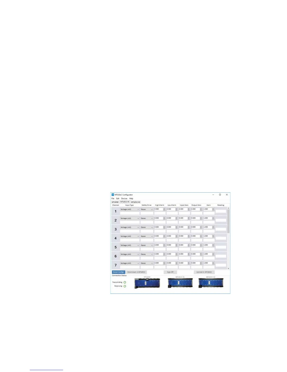
5.3 The MTL831C #1 Tab
This tab contains the configuration for the MTL831C at address #1 (the unit
without the address jumper). Below is what the tab looks like when not connected
to the PC.
Figure 3 - Configuration for 831C at Address #1 screen
This tab is arranged in rows and columns. Each row is a different channel – ranging
from 1 through 16 plus a 17th row labeled CJ (Cold Junction). Each numbered row
corresponds to that numbered channel on the MTL831C unit. The following explains
the column items for channels. In each row, the white rectangular boxes would
contain the current setting in the unit that is being communicated with. They are
blank because no unit is currently connected.
 Loading...