6 type vsa12, vsa12b, vsa16, vsa20, and vsa20a operation and installation instructions MN280063EN May 2017
240 vac power connections
A 240 Vac power source is required to operate the recloser.
A 120 Vac input power supply accessory is also available.
The source is brought into the operator mechanism cabinet
and connected to the terminal block mounted on the left
side wall of the cabinet. The terminal block is permanently
wired to the circuit-fused disconnect and the heater control
panel. Two 2 A fuses are included on the heater control
panel.
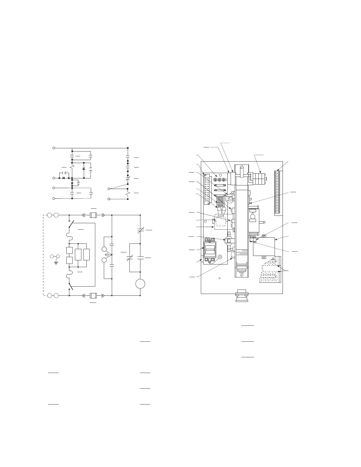
A schematic diagram of the recloser circuit and the
physical arrangement of the operator mechanism, with
parts identified, is shown in Figure 4. Figure 5 is an
interconnection diagram.
Remove recloser from service
1. Block ground tripping via the control panel.
2. Close all three bypass switches.
3. With a hotstick, pull down the yellow MANUAL TRIP
PULLRING under the cabinet.
4. The control will sense that the recloser is open.
5. Open the source and load disconnect switches.
6. Follow standard utility procedures regarding removal of
recloser from service.
AS Auxiliary Switch 152 Spring Position Switch (24 Vdc) SP1
152
CC
Close Coil (Solenoid)
D Diodes 1N3209
152
SP2
Spring Position Switch
(240 Vac) Close Motor Circuit
152
MCS
Manual Close Switch
C Surge Capacitor M Motor
152
LS
Contact for Manual Limit
Switch - Trip and Reset
FU
20
Fuse Box 1R Socket
152
aa1
Cam-Operated Switch
Open Motor Circuit
V Varistor
2R Recloser Receptacle
152
bb1
b Contact to Close Closing
Circuit
CH Mechanism Cabinet Heater
152
a1
a Contact to Open Trip Coil
152
TC
Trip Coil (Solenoid) IEH Interrupter Enclosure Heater
152
SP1
152
bb1
152
LS
152
CC
F
ED
C
B
A
152
a2
152
a1
8
75
6
1
2 4
3
N
152
TC
Trip Circuit Closing Circuit
24 Vdc
ELECTRONIC CONTROL
"M"
13
16
NO
152
aa1
15
NC
14
152
MCS
152
SP2
C
C
V
V
2
3
1
31
FU
2AMP
TYPE FRN-R2
H
1
2TB
GND
2TB
H
2
FU
2 AMP
TYPE
AGC-1
FU
2 AMP
TYPE
AGC-1
Cabinet Heaters
1K
1K
Enclosure Heaters
FU
2 AMP
TYPE FRN-R2
2 4
NO
Motor Closing Circuit
240 Vac
.5K
.5K
IEH
IEH
CHCH
152
TC
1TB
152
bb1
152
aa1
152
CC
2TB
M
2R
4TB
(24 V)
(230 V)
CH
152
LS
3TB
A S
152
a2
152
a1
D
V
152
MCS
FU
2.0
152
SP1
152
SP2
C
1R
Figure 4. Schematic diagram of recloser circuits and approximate location of circuit components.

 Loading...


