Reactive Current
Real Current (% of C.T. Primary)
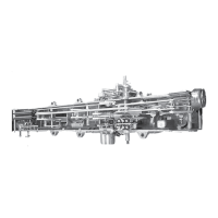
Forward Operation =
2% 0
Band edge indicators
are turned off and tap
changing is inhibited
when real component
of current is greater
than 2% reverse.
Figure22. Locked forward mode operation
OPERATION: See Figure22. Voltage regulation always
occurs in the direction from the source bushing to the load
bushing. Voltage regulation operation will use the forward
direction settings at FC 1, FC 2, FC 3, FC 4, and FC 5.
Voltage regulation operation will occur down to a zero
current condition because the reverse current sense
threshold is not applied. As a safeguard, the locked forward
setting is programmed to prevent voltage regulation
runaway in the event reverse power flow does occur. If
reverse current exceeds 2% of the CT primary, the control
idles on the last tap position held and the band edge
indicators will turn off. The control will also go into an
auto tap blocking state and display Rev Pwr Mode on the
Load Current Metering-PLUS screen. As the current flow
returns to a level above the 2% safeguard, normal forward
operation resumes.
Locked reverse mode
The Lock Reverse setting is intended for applications where
forward power flow is not possible. When the control is
set for Locked Reverse, a measured or calculated voltage
from the source bushing is required. A voltage from the
load bushing is also required for the measurement and
calculation methods of determining the source bushing
voltage.
METERING: Always determined in the reverse direction,
regardless of power flow direction. If forward power occurs,
the metering functions remain on the source-bushing side
of the regulator and no forward demand readings will occur.
OPERATION: See Figure23. Voltage regulation always
occurs in the direction from the load bushing to the source
bushing. Voltage regulation operation will use the reverse
direction settings at FC 51, FC 52, FC 53, FC 54, and FC 55.
Voltage regulation operation will occur down to a zero
current condition because the reverse current sense
threshold is not applied. As safeguard, the locked reverse
setting is programmed to prevent voltage regulation
runaway in the event forward power flow does occur. If
forward current exceeds 2% of the CT primary rating, the
control idles on the last tap position held and the band edge
indicators will turn off. The control will also go into an auto
tap blocking state and display Rev Pwr Mode on the Load
Current Metering-PLUS screen. As the current flow returns
to a level above the 2% safeguard, normal reverse operation
resumes.
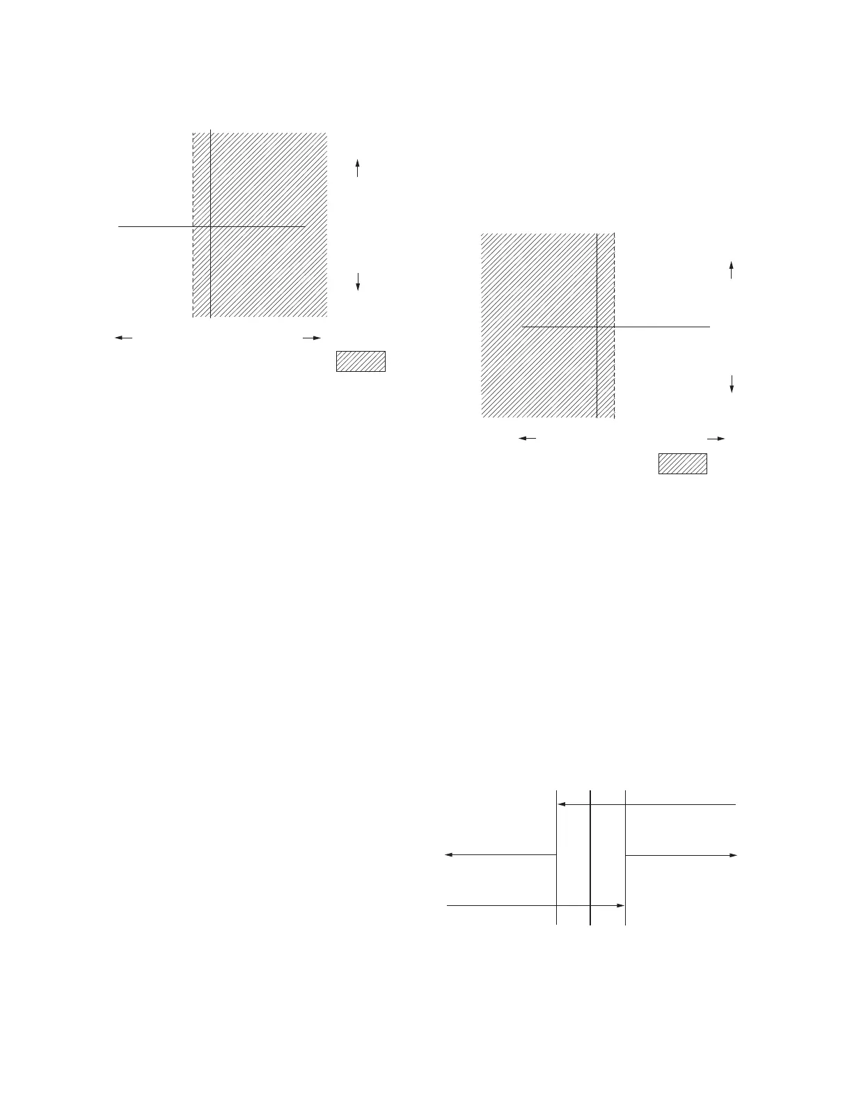
Reactive Current
Real Current (% of C.T. Primary)
Reverse =
2%0
Figure23. Locked reverse mode operation
Reverse idle mode
The Reverse Idle setting is recommended for applications
where reverse power is possible but the source bushing
voltage cannot be determined and reverse power regulation
is not required. When the control is set for Reverse Idle, a
measured or calculated source voltage would be needed for
metering only.
METERING: See Figure24. A threshold level of 1% (.002
A) of the full load CT secondary current of .200 A is used
in setting the power direction. The metering will be forward
until the current exceeds the 1% threshold in the reverse
direction. At this time, the various parameters use the
reverse settings and the Reverse Power indicator turns on.
The control continues metering in reverse until the current
exceeds the 1% threshold in the forward direction, and
then the parameter scaling reverts back to normal and the
Reverse Power indicator turns off.
Normal Forward
Metering
Rev Pwr Off
Reverse Metering
Reverse Scaling
Rev Pwr On
Current Level
1% 0 1%
Figure24. Reverse idle metering
126
INSTALLATION, OPERATION, AND MAINTENANCE INSTRUCTIONS MN225003EN April 2018
CL-7 Voltage Regulator Control
 Loading...