Reactive Current
Real Current (% of C.T. Primary)
Forward Operation =
0
OT
OT=Operating Threshold, FC 57, 1-5%
Tap changing inhibited
when total current is
within operating thresholds.
Reverse Operation =
OT
+
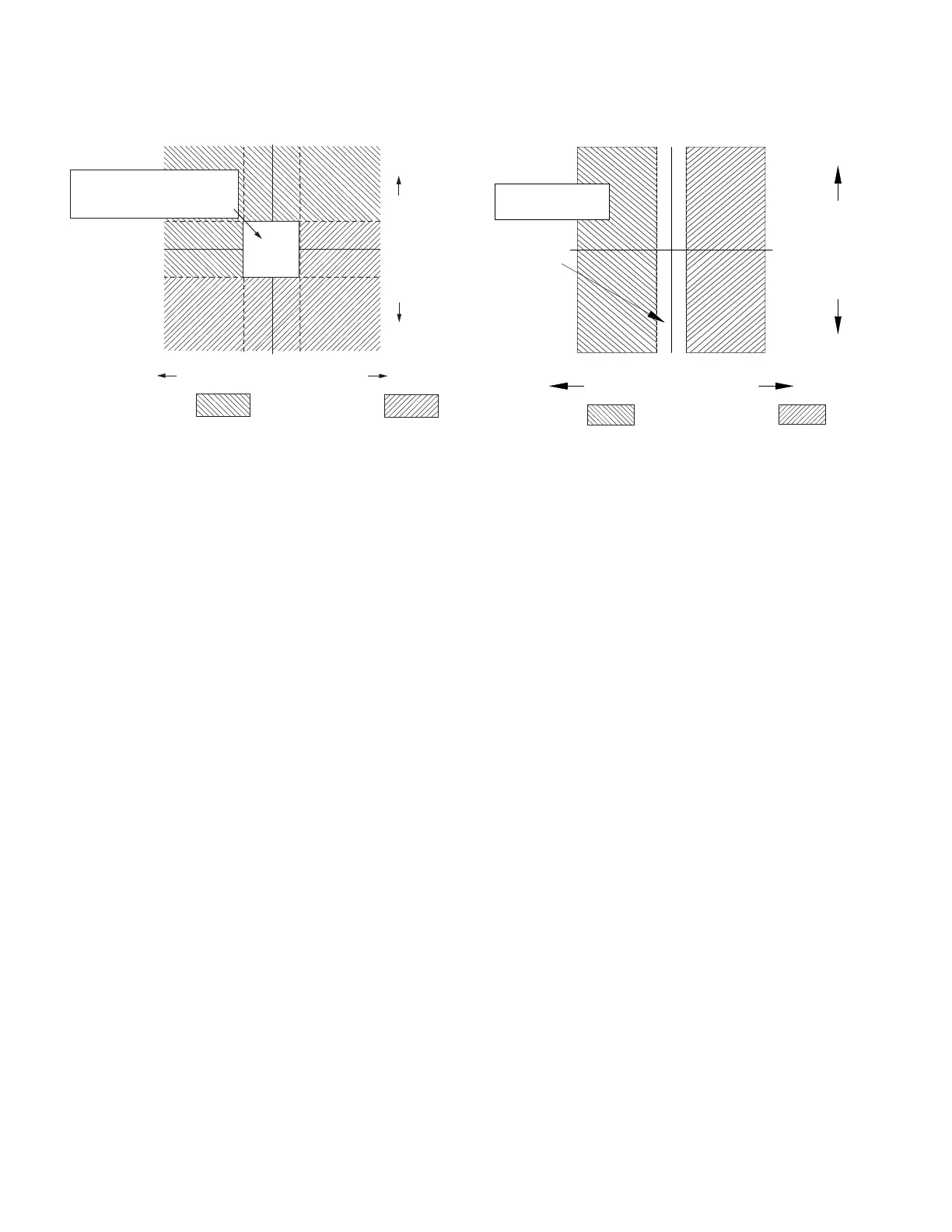
Figure32. Reactive bi-directional mode operation
Bias bi-directional mode
When FC 56 is set for Bias Bi-directional, a source voltage
is required, either measured or calculated. This mode is
an option for installations where reverse power flow may
occur except where the source of reverse power is a
co-generation facility or independent power producer. This
mode is similar in operation to the Bi-Directional Mode,
but includes a mechanism to enable voltage regulation
when current flow is below the current sense threshold
and current flow direction cannot be reliably determined
because of CT accuracy limitations.
METERING: When current direction is above the current
threshold in the forward direction or below it in the reverse
direction, metering will be recorded in the direction of
current flow. When current flow is under the current
thresholds for forward and reverse power, the control
will use a mechanism that includes tapping and sampling
changes in voltage to look for an out-of-band condition.
Metering will be recorded for the current direction last
determined by the sampling mechanism to be correct.
Real Current (% of C.T. Primary)
OT
Forward Operation =
OT = Operating Threshold, FC 57, 1-5%
OT
0
Bias regulation
in direction of
power before
indeterminate
state was
entered.
Normal Reverse
Operation FC 51-55
Figure33. Bias bi-directional mode operation
OPERATION: See Figure33. In Bias Bi-directional Mode,
the control shall function in the power flow direction it was
in before entering the indeterminate state. If the control
was in the forward power direction before it entered
the indeterminate state, it shall use forward settings to
determine if it is out of band. If the control was in the
reverse power direction before it entered the indeterminate
state, it shall use reverse settings to determine if it is out of
band.
Any time the control is in the indeterminate state and
transitions from an in-band to an out-of-band condition, it
will make two quick steps to determine if it is tapping in the
correct direction for the flow of power. The two quick steps
will be in the appropriate direction based upon the last
known power direction.
ote:N In the context of this discussion, the quick raise
steps would be in the clockwise direction on the
position indicator and quick lower steps would be in
the counter-clockwise direction.
The control shall confirm it is tapping in the correct direction
if any one of following conditions is met:
Load bushing voltage increases one percent or more of
the nominal secondary voltage after two quick raise taps
if the control is out of band low and was in the forward
direction before it entered the indeterminate state, or
Load bushing voltage is unchanged or increases less
than one percent of the nominal secondary voltage after
two quick raise taps if the control is out of band high
and was in the reverse direction before it entered the
indeterminate state, or
130
INSTALLATION, OPERATION, AND MAINTENANCE INSTRUCTIONS MN225003EN April 2018
CL-7 Voltage Regulator Control
 Loading...