Status
Indicators
USB Drive and
PC Data Ports
Multi-phase
Indicators
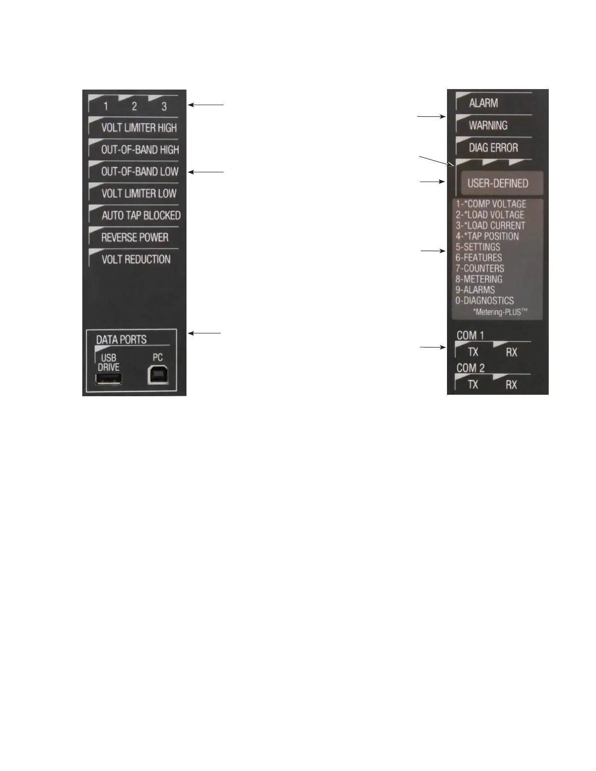
Figure11. Status indicators and USB ports
Indicator LEDs
Multi-phase indicators
These LEDs provide an indication of which connected voltage
regulator is active for the parameter displayed on the LCD
screen and for the Status Indicator LEDs. Pressing the right
arrow key will scroll through the LEDs. They are active and
used only for multi-phase functionality. Refer to Figure11.
Status indicators
These LEDs indicate regulation conditions: Voltage
Limiter High, Out-of-Band High, Out-of-Band Low, Voltage
Limiter Low, Tapping Blocked, Reverse Power, and Voltage
Reduction. Refer to Figure11.
Alarm indicators
These LEDs indicate an Alarm, Warning, user-defined
condition, or a diagnostic error. See Figure12.
Communications indicators
These LEDs illuminated to indicate transmit (Tx) and receive
(Rx) activity when the transfer of information is taking
place through the communications ports on the side of the
control. See Figure12.
Alarm Indicators
User Defined LEDs
User Defined LED
Description Slide-out
Hot-Key Description
Slide-out
Communication
Indicators
Figure12. Alarm, communication indicators and slide-
out hot-key map
Data ports
USB drive
The USB Drive data port accepts any USB 2.0 compatible
memory device that is formatted with the FAT32 file
system. It is used to download data logs and to load and
save settings files. See Figure11. USB functionality can be
accessed in the top-level menu item USB MEMORY DRIVE
or directly using FC 950 through FC 953. See Section7:
Advanced Control Features: USB memory device for
more information. The LED above the port illuminates to
indicate an active connection between the control and USB
memory Drive.
PC
The PC data port is a USB type B port that interfaces
local communication between the control and a PC using
a standard USB type A to B printer cable. See Figure11.
The purpose of the port is for communications between
a control and a PC loaded with ProView NXG software.
The green data ports LED will flash when communications
traffic is being processed through the PC data port.
Hot-key mapping
This slide out card provides information about the hot key
mapping assignments. See Figure12.
13
INSTALLATION, OPERATION, AND MAINTENANCE INSTRUCTIONS MN225003EN April 2018
CL-7 Voltage Regulator Control
 Loading...