Page 1 (60) Motor Pump Enhanced Protection Application SV9000
1 General
The Motor Pump Enhanced Protection
application is a modified version of the normal
Multi-Purpose application. It has parameters for
torque control and for Fieldbus communication.
The following fieldbuses are supported:
Interbus, Modbus, LonWorks, CAN-bus
(SDS, DeviceNet).
The frequency reference, the analog and
digital outputs have extra alternatives in their
control parameters, however, the source of the
free analog input can not be selected from the
I/O Expander as in the Multi-Purpose II
application. Lastly, this application allows for
up to four (4) additional custom inputs, faults,
and fault indicators (when an additional I/O
board is installed).
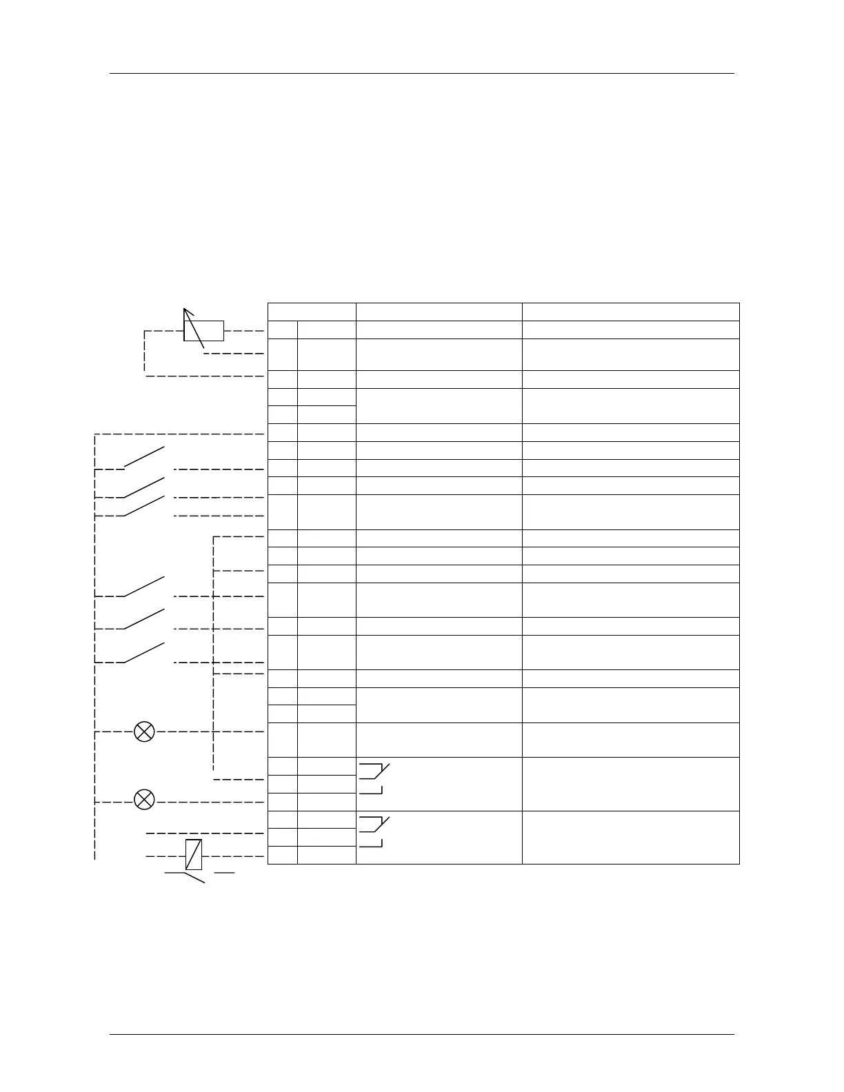
2 Control I/O
Terminal Signal Description
1 +10V
ref
Reference output Voltage for potentiometer, etc.
2V
in
+
Analog input, voltage
(programmable)
Frequency reference range 0—10 V
DC
3 GND I/O Ground Ground for reference and controls
4I
in
+
5I
in
-
Analog input,
current (programmable)
Default setting: not used,
range 0—20 mA
6 +24V Control voltage output Voltage for switches, etc. max 0.1 A
7 GND I/O ground Ground for reference and controls
8 DIA 1 Start forward Contact closed = start forward
9DIA 2Programmable InputContact closed = Enable 11.1.3
10 DIA 3 Fault reset Contact open = no action
Contact closed = fault reset
11 CMA Common for DIA 1—DIA 3 Connect to GND or +24V
12 +24V Control voltage output Voltage for switches (see #6)
13 GND I/O ground Ground for reference and controls
14 DIB4 Jog speed select
(programmable)
Contact open = no action
Contact closed = jogging speed
15 DIB5 Programmable Input Default = Not Used
16 DIB6 Acceleration/deceleration
time select (programmable)
Contact open = par. 1.3, 1.4 in use
Contact closed = par. 4.3, 4.4 in use
17 CMB Common for DIB4—DIB6 Connect to GND or +24V
18 I
out
+
19 I
out
-
Output frequency
Analog output
Programmable, (par. 3.1)
Range 0—20 mA/R
L
, max. 500Ω
20 DO1 Digital output
READY
Programmable, (par. 12.1)
Open collector, I≤50mA, U≤48 VDC
21 RO1
22 RO1
23 RO1
Relay output 1
RUN
Programmable, (par. 12.2)
24 RO2
25 RO2
26 RO2
Relay output 2Programmable, (par. 12.3)
Default = Not used
Figure 2-1 Default I/O configuration and connection example of the
Motor Pump Enhanced Protection Application
220
VAC
 Loading...


