SV9000 Motor Pump Enhanced Protection Application Page 5 (60)
5.2 Description of Group 1 Parameters
1.1 Minimum frequency
1.2 Maximum frequency
Defines frequency limits of the frequency converter. The default maximum value for
parameters 1.1 and 1.2 is 120 Hz. By setting 1.2 = 120 Hz when the device is stopped
(RUN indicator not lit) the maximum value of parameters 1.1 and 1.2 is changed to
500 Hz. At the same time the panel reference resolution is changed from 0.01 Hz to
0.1 Hz. Changing the maximum value from 500 Hz to 120 Hz is done by setting parameter
1.2 = 119 Hz when the device is stopped.
1.3 Acceleration time 1
1.4 Deceleration time 1
These limits correspond to the time required for the output frequency to accelerate from
the set minimum frequency (par. 1.1) to the set maximum frequency (par. 1.2).
1.5 Reference selection
0 Analog voltage reference from terminals 2—3, e.g. a potentiometer
1 Analog current reference from terminals 4—5, e.g. a transducer.
2 Reference is formed by adding the values of the analog inputs
3 Reference is formed by subtracting the voltage input (V
in
) value from the current input
(I
in
) value
4 Reference is formed by subtracting the current input (I
in
) value from the voltage input
(V
in
) value
5 Reference is the formed by multiplying the values of the analog inputs
6 Joystick control from the voltage input (V
in
).
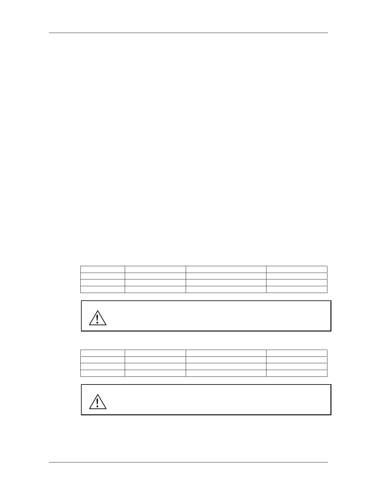
Signal Range Max Reverse Speed Direction Change Max Forward Speed
0—10 V 0 V 5 V +10 V
Custom Par. 2.2 x 10V In the middle of custom range Par. 2.3 x 10 V
-10 V—+10 V -10 V 0 V +10 V
Warning! Use only the -10V—+10 V signal range. If a custom or 0—10 V signal range
is used, the drive starts to run at the maximum reverse speed if the reference
signal is lost.
7 Joystick control from the current input (I
in
).
Signal Range Max Reverse Speed Direction Change Max Forward Speed
0—20 mA 0 mA 10 mA 20 mA
Custom Par. 2.8 x 20 mA In the middle of custom range Par. 2.9 x 20 mA
4—20 mA 4 mA 12 mA 20 mA
Warning! Use only 4—20 mA signal range. If custom or 0—20 mA signal range is
used, the drive runs at maximum reverse speed if the control signal is lost.
Set the reference fault (par. 7.2) active when the 4—20 mA range is used,
then the drive will stop to the reference fault if the reference signal is lost.
Note! When joystick control is used, the direction control is generated from the joystick
reference signal. See figure 5.2-1.
 Loading...


