5 Installation and Start-up
5.1
Installation
Personnel:
n
Mechanic
n
Service personnel
n
Specialist
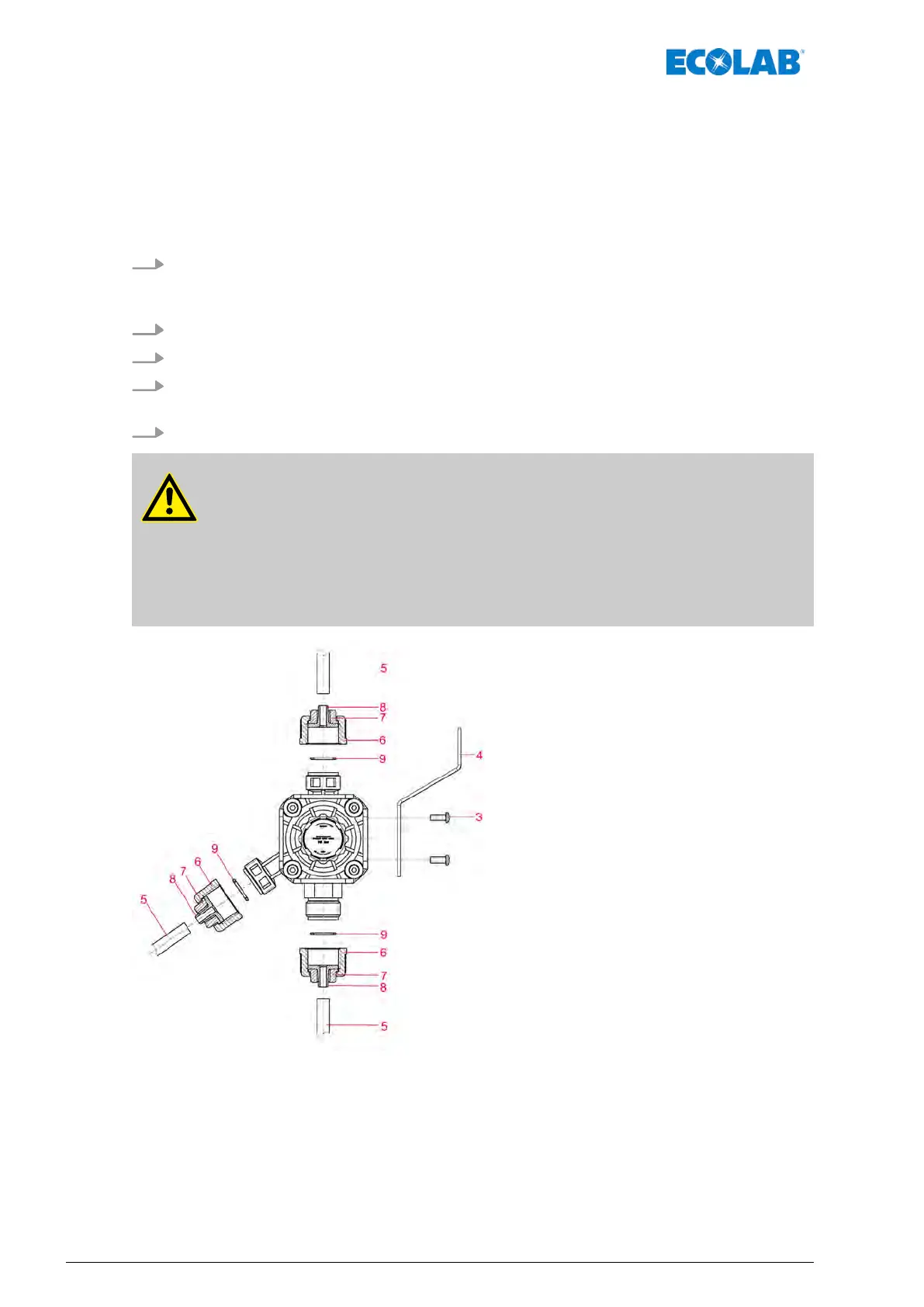
1. Mount the multifunction valve (Pos. 3) on the mounting bracket (Pos. 4) or similar
mounting plate by means of the enclosed plastic self-tapping screws. Fix the
mounting bracket to a wall.
2. Connecting the metering and return line.
3. Cut the hose (Pos. 5) evenly
.
4. Place the union nut (Pos. 6) and the thrust piece (Pos. 7) over the hose up to the
stop collar on the connection nipple (Pos. 8).
5. Place the o-ring (Pos. 9) in the o-ring-nut and tighten the union nut (Pos. 6).
CAUTION!
The return line (venting line) must always be connected. The multiple
function valve is not an absolute sealing shut-of
f device. The minimal cross
section must correspond to the valve size (
Ä
Chapter 9 ‘Technical Data’
on page 30).
In the case of dosing media which tend to crystallize, the overpressure
function cannot be guaranteed under certain circumstances.
Fig. 2: Installation
3 Plastic self-tapping screw
4 Mounting bracket
5 Hose
6 Union nut
7 Thrust piece
8 Connection nipple
9 O-ring
Installation and Start-up
22417101224 Rev. 05-05.2019
 Loading...