(Figure3‐1n.13)to
increaseorreducethe
speed
correspondstoneutralandthensoontothefirstgear,second,third,fourthandfifth.
Tomovethemachinewiththemotoroff shift theleverto(Figure3‐2no.8)the
neutralpositionandactivatetheforward
movementleverengagement(Figure3‐2
no.9).
Steering Usesufficientpressureonthehandgripsto
turnrightorleft.
Themachineisequippedwithtwolevers,oneontheleftofthehandlebarandthe
otherontheright.Thesecontrolthelockingofthetwowheelsemi‐axles(Figure3‐2
no.5/no.10).
Lightlyactivatingthesetwolevers,allowsthecorrespondingwheelto
turnfreely,whilsttheothercontinuesasadrivewheelenablingthemachinetomake
alargeradiusturnandtocorrectthereforethemachine'strajectoryinasmooth
mannerwithoutjolts.Pullingthesamelevertoitsfullstroke
insteadactsonthe
lockingofthewheelwhilsttheothercontinuesasadrivewheelensuringthatthe
machineturnsonitselfwhenthereisanobstacleorbrokenandunmanageable
groundinfrontofit.
Handlebar
height
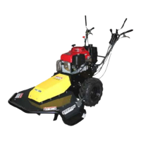
N/A Thehandlebarscanbeadjustedtofivedifferentheights.Toadjusttheheightusethe
righthandexternallever(Figure3‐2no.4)thenadjustthecorrespondingpinsinone
ofthefiveheightadjustmentholes(Figure6‐1no.15)
15‐ Handlebarheightadjustmentpin
16‐Handlebarendstrokescrew
Figure6‐1:Handlebarheight
Slope N/A Themachineenablesthree
inclinationanglestothe
rightandthreetotheleft.
Toadjusttheinclination
anglesusetheredlefthand
lever(Figure3‐1no.4)then
adjustthecorrespondent
pinsinoneoftheseven
angleadjustmentholes(no.
15)
N/A Themachine
enables
four
inclinationangles
totherightand
fourtotheleft.To
adjustthe
inclinationangles
usetheexternal
lefthandlever
(Figure3‐2no.11)
thenadjustthe
corresponding
pinsinoneofthe
nineangle
adjustmentholes.
N/A Themachineenables
fourinclinationanglesto
therightand
fourtothe
left.Toadjustthe
inclinationanglesuse
theexternallefthand
lever(Figure3‐2no.11)
thenadjustthe
correspondingpinsin
oneofthenineangle
adjustmentholes.
Motor Refertothemotorinstructionmanual.
Table6‐1:Adjustments
6.2 OPERATIONALMODES
6.2.1 WORKINGONLEVELGROUND
Afterhavingperformedthepreliminarychecksreferredtoinpoint4.3andafterstarting
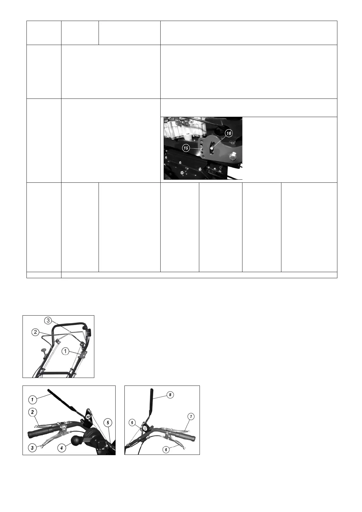
themotor,activatethebladecouplinglever(Figure6‐2–no.2;Figure6‐3–n.8),select
the gear in which you want to work (depending on the models), engage the forward
movementlever
(Figure6‐2–no.3;Figure6‐3–n.1)andbeginworkusingthegreatest
careatalltimes.
Figure6‐2:HandlebarsforModelTRT60/TRT60Swing
Figure6‐3:HandlebarsforModelTRT110‐
135/TRT110‐135Swing
 Loading...