Do you have a question about the ECS Mainboard and is the answer not in the manual?
| Brand | ECS |
|---|---|
| Model | Mainboard |
| Category | Motherboard |
| Language | English |
Keep mainboard and components in original static-proof packaging until ready for installation.
Wear a grounded wrist strap or discharge static by touching system chassis.
Hold the mainboard by its edges, avoiding touching components.
Check mainboard components and connectors for any visible damages.
Do not connect power if damage is suspected; contact vendor.
Details support for Intel Pentium 4 CPUs with Hyper-Threading Technology.
Instructions to initiate Hyper-Threading CPU function via BIOS setup.
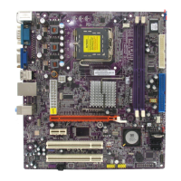
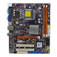
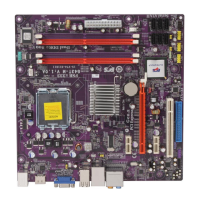
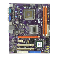
Details support for Intel Pentium 4 CPUs and up to 800 MHz Front-Side Bus.
Specifies support for two 184-pin DDR SDRAM DIMM sockets, up to 2GB DDR400.
Provides three 32-bit PCI expansion slots.
Includes one 8x AGP slot for graphics adapters.
Equipped with two IDE connectors for storage devices.
Includes two PS/2 ports for connecting a mouse and keyboard.
Offers six USB 2.0 ports (four back-panel, two via connector).
Compliant with the Universal Serial Bus Specification Revision 2.0.
AMI BIOS allows configuration of power management, wake-up alarms, and CPU/memory timing.
Adjust CPU parameters and memory timings through BIOS setup.
The CD-ROM containing software, drivers, and utilities.
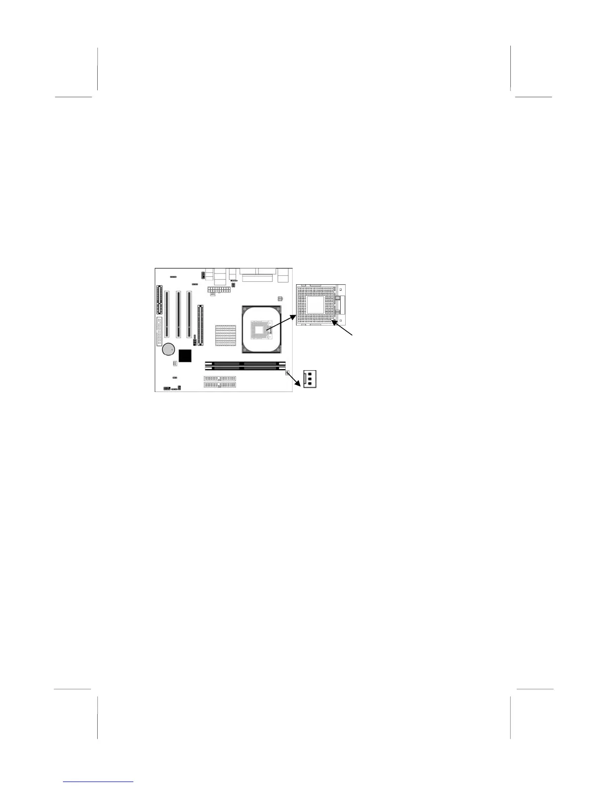
Procedure for installing the Central Processing Unit (CPU).
Instructions for installing system memory modules (DIMMs).
Ensure all jumpers and switches are set to the correct configuration.
Steps for mounting the mainboard into a computer system chassis.
Verify that jumper JP2 is set to the 'Normal' setting before installation.
Never connect power to the system during installation to prevent damage.
Use the upper PS/2 port for connecting a PS/2 pointing device.
Use the lower PS/2 port for connecting a PS/2 keyboard.
Description of Parallel (PRN) and Serial (COM1) ports.
Use the USB ports to connect USB devices.
Use the three audio ports for Line-In, Line-Out, and Microphone.
Steps include unlocking socket, aligning CPU, securing lever, applying grease, installing heatsink/fan, and connecting fan power.
Supports two 184-pin DDR SDRAM DIMM sockets, up to 2.0 GB of 400 MHz DDR SDRAM.
Push down the latches on both sides of the DIMM socket to open it.
Align the memory module with the socket notch for correct orientation.
Insert the DIMM module firmly until socket latches engage.
Repeat the process for any other DIMM modules to be installed.
Use this jumper to clear the CMOS memory if settings are incorrect.
These jumpers select the voltage for USB ports.
Install the Micro ATX mainboard in an ATX case, ensuring I/O cover plate alignment.
Adhere to the case manufacturer's instructions for hardware and mounting points.
Connect the main power supply connector to the ATXPW1 on the mainboard.
Connect the CPUPW1 connector for the CPU Vcore power.
Connect chassis cooling fan cable to the SYSFAN1 connector.
Connect case switches and LEDs to the PANEL1 connector using pin assignments.
Connect front panel microphone and line-out ports to the AUDIO2 connector.
Connect devices to the Primary IDE channel connector (IDE1) using the provided cable.
Steps for installing AGP, CNR, or PCI expansion cards.
Incorrect BIOS settings can cause system malfunction or prevent booting.
Clear CMOS jumper or holding 'Page Up' key can reset BIOS configuration.
Manually change system configuration settings for hardware like CPU, memory, and drives.
Press the <DEL> key during boot when prompted to enter BIOS Setup.
Key bindings for navigation (arrows, Enter, +/-, Esc) and saving (F10).
Press F10 to save changes and exit the BIOS Setup Utility.
Configure IDE devices (Master/Slave) or set to Auto/User/CDROM/Floptical.
Determine the order of devices the system checks for loading the operating system.
Select graphics controller (PCI or AGP) as the primary boot device.
Access sub menu to change the supervisor password.
Enable to automatically detect CPU and DRAM frequencies.
Option to load optimized defaults for best performance.
Users are highly recommended to load optimal defaults for best performance.
Save changes made in the Setup Utility by highlighting and pressing Enter.
Confirm saving changes and exiting by pressing 'Y', or return to menu with 'N'.
Discard any changes made in the Setup Utility and exit.
Confirm discarding changes by pressing 'Y', or return to menu with 'N'.
Use 'Discard Changes and Exit' and press 'Y' to discard unsaved settings.
Click 'Setup' on the Auto Setup screen to run the software auto-installing program.
Follow manual installation steps if auto-install fails or for Windows NT.
Hyper-Threading Function works only under Windows XP; disable on other OS.